FORM NO. 56043093 / Captor
™
4300, 4800, 5400 - 69
HYDRAULIC SYSTEM
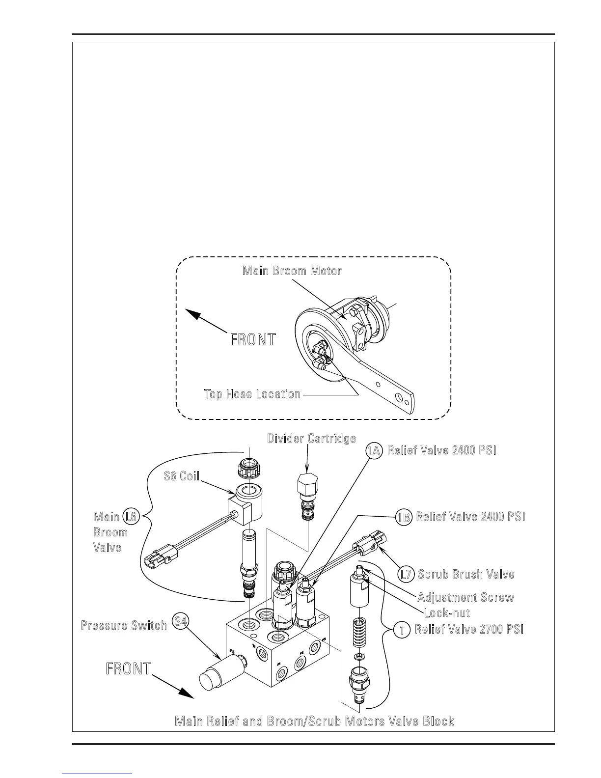
FIGURE 3
SETTING RELIEF VALVE PUMP CIRCUIT 1
Cap and plug broom drive motor inlet hose # 56 (top hose from B port valve block).
Raise hopper and install a metal washer to the magnetic hopper switch (S12).
Open engine hopper door panel to access pump relief valve block assembly.
Connect adapter cord PN 56407502 to L6 Main Broom solenoid coil (wire colors ORG & GRN/GRY).
Insert hydraulic test gauge (3000psi) to the XT 1 test port.
To adjust the hydraulic oil must be warm and engine in high speed (2400rpm).
Energize L6 main broom solenoid using the adapter cord. The pump circuit 1 will be in overload use caution not to leave in this
position for a long period, may cause damage.
Observe the pressure gauge and adjust accordingly. Relief should be at 2700psi. Loosen Lock-nut, turn Adjustment Screw CCW to
decrease pressure CW to increase.
FRONT
Relief Valve 2700 PSI
vacuum fan & main broom
1
1A
1B
Relief Valve 2400 PSI
engine fan, steering, dump door,
hopper lift, side brooms & dust
control
R
elief Valve 2400 PSI
scrub brushes, squeegee
lift & scrub lift
Divider Cartridge
L6
Pressure Sw itch
main broom/vac fan
S4
Main
Broom
Valve
L7
Scrub Brush Valve
S6 Coil
Adjustment Screw
Lock-nut
Top Hose Locati on
FRONT
Main Bro om Motor
Main Relief and Broom/Scrub Motors Valve Block
 Loading...