D
f s
Nil i
k
AL
T
O
Bud
y/A
e
ro_
V
r.
1.
0_
1
7
106
d
e
0
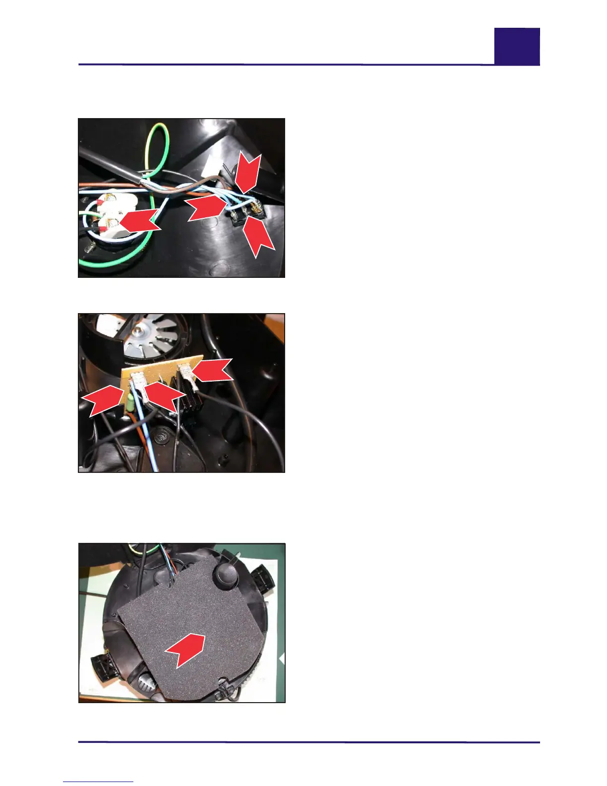
3.6 Disassembling/assembling the start-up unit
1.) Remove the cover (see D/3.1, page 14).
2.) Disconnect the brown (1), blue (1) and black
(1) leads from the switch.
3.) Disconnect the black lead (2) from the socket
and pull it off.
4.) Lift the insulating material out of the cover
(see D3.7, page 17).
5.) Disconnect the two motor leads (3) from the
start-up unit (4).
6.) Pull the unit (4) upwards out of its holder and
remove it.
7.) Assemble in the reverse order.
Start-up unit / clamping plate
3.7 Disassembling/assembling the clamping plate
1.) Remove the cover (see D/3.1, page 14).
2.) Lift out the insulating material (1).
3.) Disconnect the two motor leads from the
start-up unit (see D/3.6, page 17) and remove
the leads from the clamp.
Continued on next page
Cable connections (1+2) for start-up unit
(4) at switch and socket.
Start-up unit (4) with motor cable connec-
tions (3), mounted on clamping plate.
Insulating material (1) in place on
clamping plate.
Aero 4120
1
2
1
1
Aero 4151
1
Aero 4121
3
3
4
evc
S
r
i
e

 Loading...