D
f s
Nil i
k
AL
T
O
Bud
y/A
e
ro_
V
r.
1.
0_
1
7
106
d
e
0
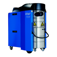
Clamping plate / motor
3.8 Disassembling/assembling the motor
1.) Disassemble the clamping plate (see D/3.7,
page 17).
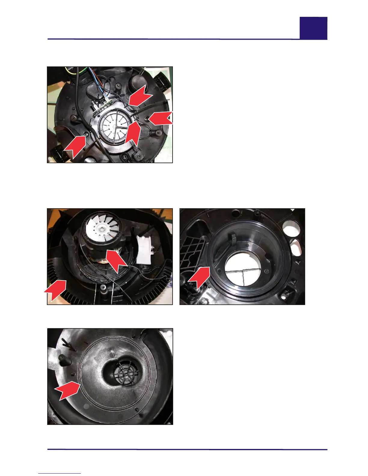
2.) Mark the position of the motor (1) in the
support plate (4) and lift out the motor (1).
3.) Assemble in the reverse order, making sure
the motor bearing rings (3+4) are positioned
correctly.
4.) Disconnect the power leads from the switch
and the socket (see D/3.3, page 15).
5.) Pull the start-up unit (4) upwards out of its
holder (see D/3.6, page 17) and remove it
together with the cover.
6.) Undo the two screws (2) from the clamping
plate with a Phillips screwdriver and lift off the
clamping plate.
7.) Assemble in the reverse order, making sure
the motor leads are located correctly in the
clamps (3).
Motor (1) in support plate (2).
Retaining screws (2) of clamping plate and
clamp (3) for motor leads.
Upper motor bearing ring (3), mounted on
clamping plate.
Lower motor bearing ring (O-ring) (4),
mounted on support plate.
Aero 4152
2
2
3
3
Aero 4131
4
Aero 4132
3
Aero 4128
1
2
evc
S
r
i
e

 Loading...