NIRx NIRSport User Manual
Page 9/18
wavelengths are emitted simultaneously and are distinguished by modulating and demodulating each at
distinct frequencies in the low kHz-range.
The instrument employs parallel readout of multiple optical detector channels, each of which uses
adaptive gain switching to maximize the dynamic measurement range). NIRSport uses innovative active
optical sensors which are placed directly on the skin, and which avoid the use of optical fiber bundles.
The device features four parallel, optically isolated digital input channels (TTL level) for the acquisition of
event trigger signals. The NIRSport instrument is operated through a graphical user interface (GUI) on a
personal computer (PC), to which it is connected by USB 2.0.
To allow time stamping of the measured data for the purpose of event synchronization with concurrent
measurements or experimental protocols, the instrument provides four parallel digital input channels.
Each of these is optically isolated from the rest of the system. Each input is over-voltage protected and
contains a comparator circuit ('Schmitt Trigger') to improve noise immunity. The inputs are TTL/CMOS
compatible and are positive-edge triggered.
4 Hardware Description
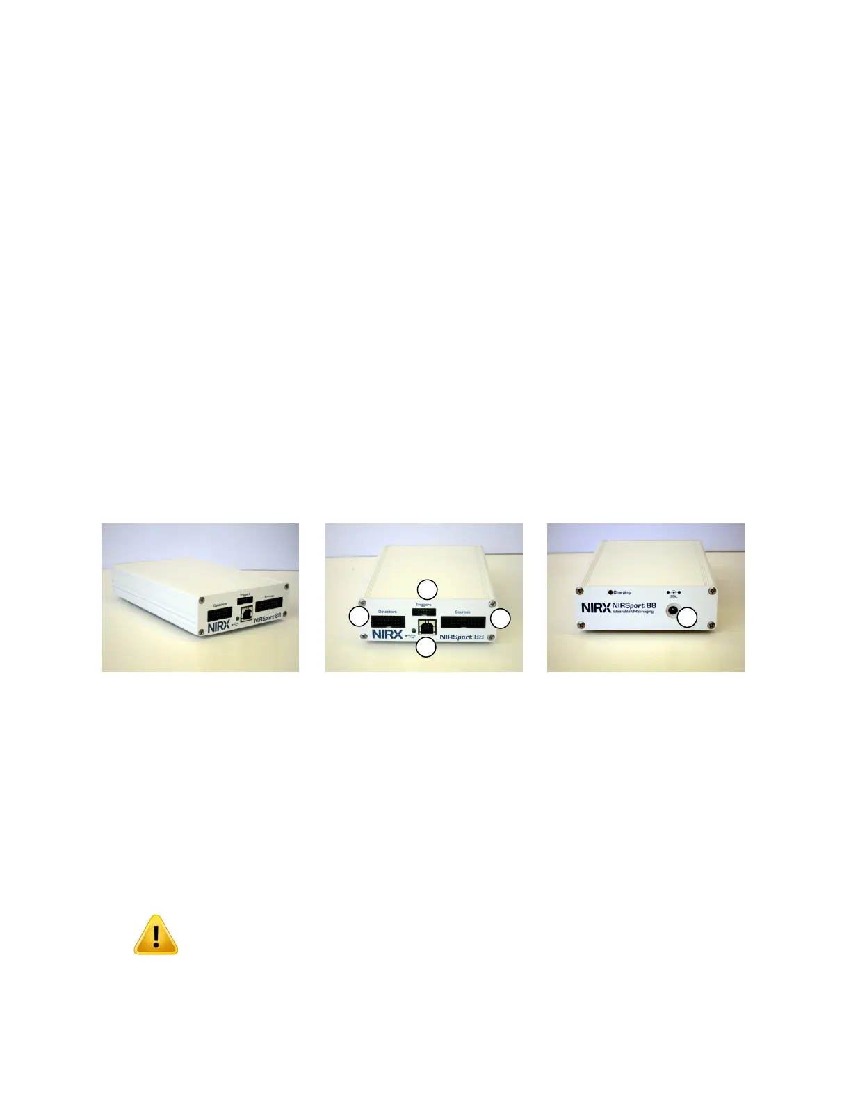
All functional components of the imager are integrated into one small form-factor enclosure to which
the sensors and control cables are attached. Fig. 1 shows the instrument.
Fig. 1. Left: NIRSport 8x8 imaging system. Center: Front panel with connectors for (1) LED sources; (2) active
detectors; (3) digital timing signals; (4) USB. Right: Rear panel with power supply connector (5).
4.1 USB Connection/Powering the Instrument
The instrument communicates with the control PC through a USB 2.0 connection. Once connected the
system goes through a startup sequence during which the green status indicator (2) lights up and then
starts to blink. At this point, the data link to the host PC is established.
A green blinking LED in the front panel signifies proper USB connection and
readiness for operation. The green LED will keep blinking all through system
operation until the USB connection is terminated.
A dark or continuously lit green LED signifies connection problems.
 Loading...