After placement, IC1 can be placed and bent over these diodes to
reduce the height of the assembled PCB. Continue to mount C1,
C2, J1 and FUSE. C1 and C2 are polarized. The longer lead goes in
the hole marked ‘+’.
4.2 Testing Low Voltage Power Supply.
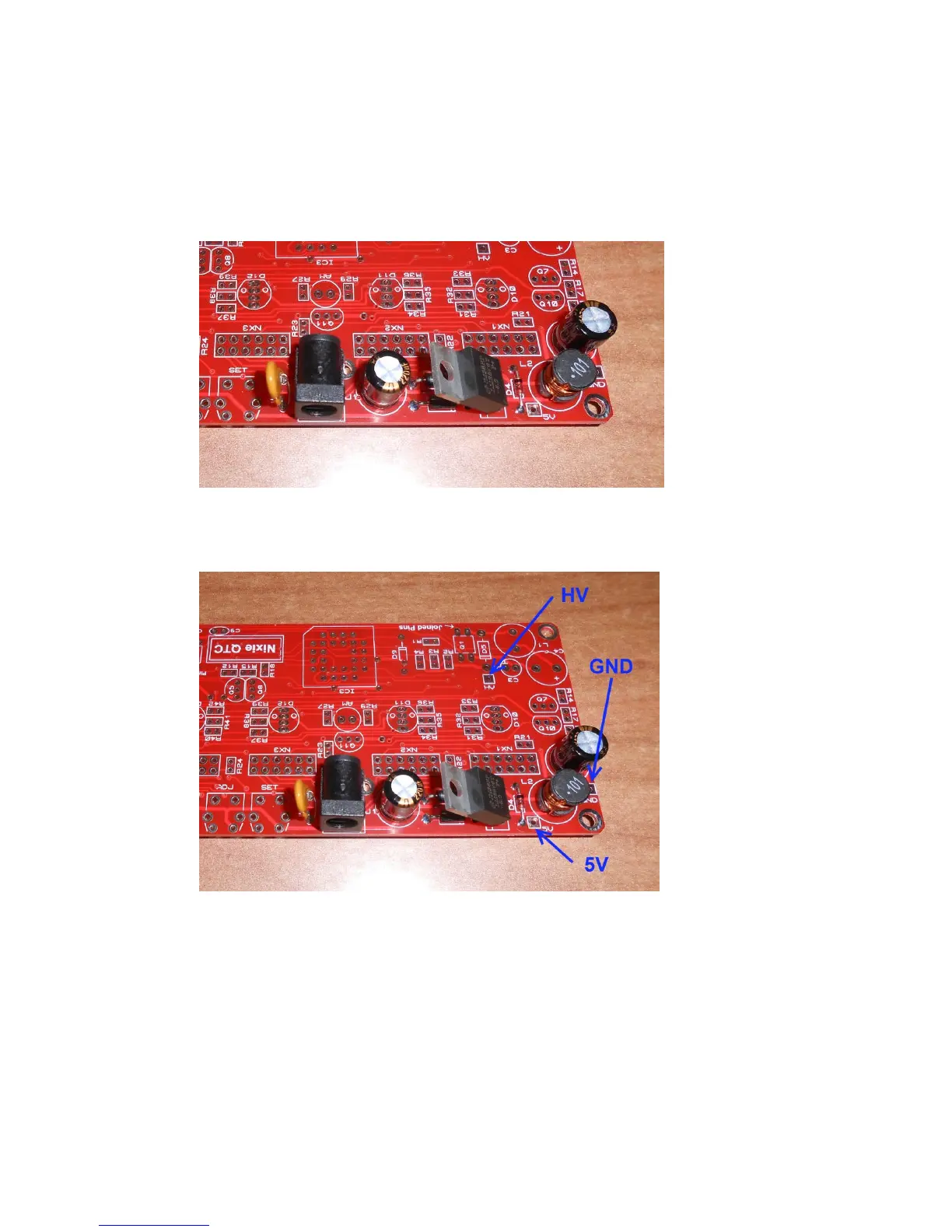
Identify the test GND, 5V and HV test points as shown below.
Plug in the power supply, and then test using a DC voltmeter:
Touch the black probe on the GND test point and the red probe on
the 5V test point. The voltage should measure between 5.6 and 5.9
Volts. If not, disconnect power and check your work. Do not
proceed with the assembly until the error is corrected. Once the
test is completed, disconnect the power.