5. ASSEMBLING THE NIXIE TUBE CELLS
PLEASE REFER TO THE APPROPRIATE SECTION FOR YOUR NIXIE
TUBE TYPE.
5.1 IN-14 Nixie Tubes.
Tube cell type: IN-14
Code configuration: A
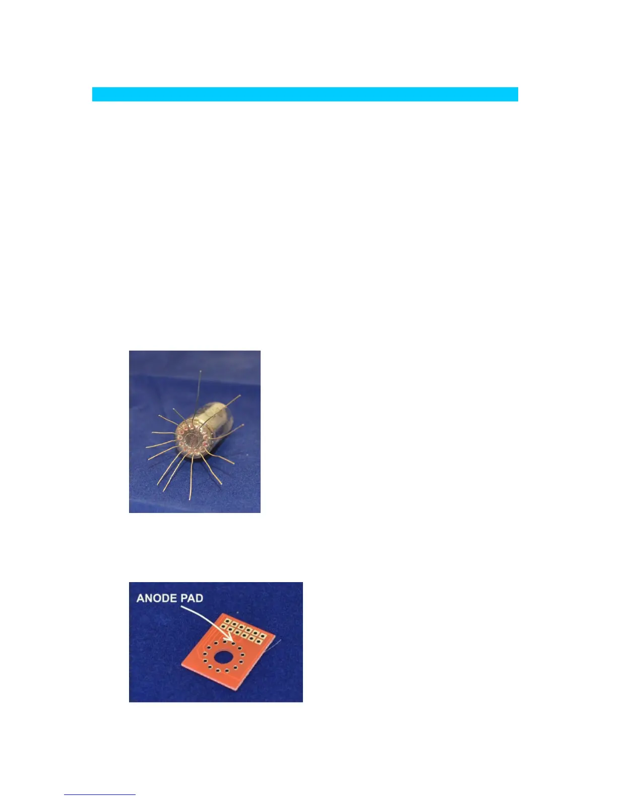
To facilitate easy insertion of the flying leads into the small holes, it
helps enormously to trim the flying leads with a pair of scissors as
shown below. Start by identifying the anode lead at the back of the
tube. It has a white coating where it enters the glass.
Then, working around the tube, cut each sucessive lead approx
2mm shorter than the previous one. This will allow you to feed
each lead in in turn.
Referring to the picture below, identify the anode pad on the tube
cell PCB. The tube is inserted from the side with no white
markings: