6. FIRST CLOCK TEST
It is now time to check the basic clock functions and that all tubes
are working correctly.
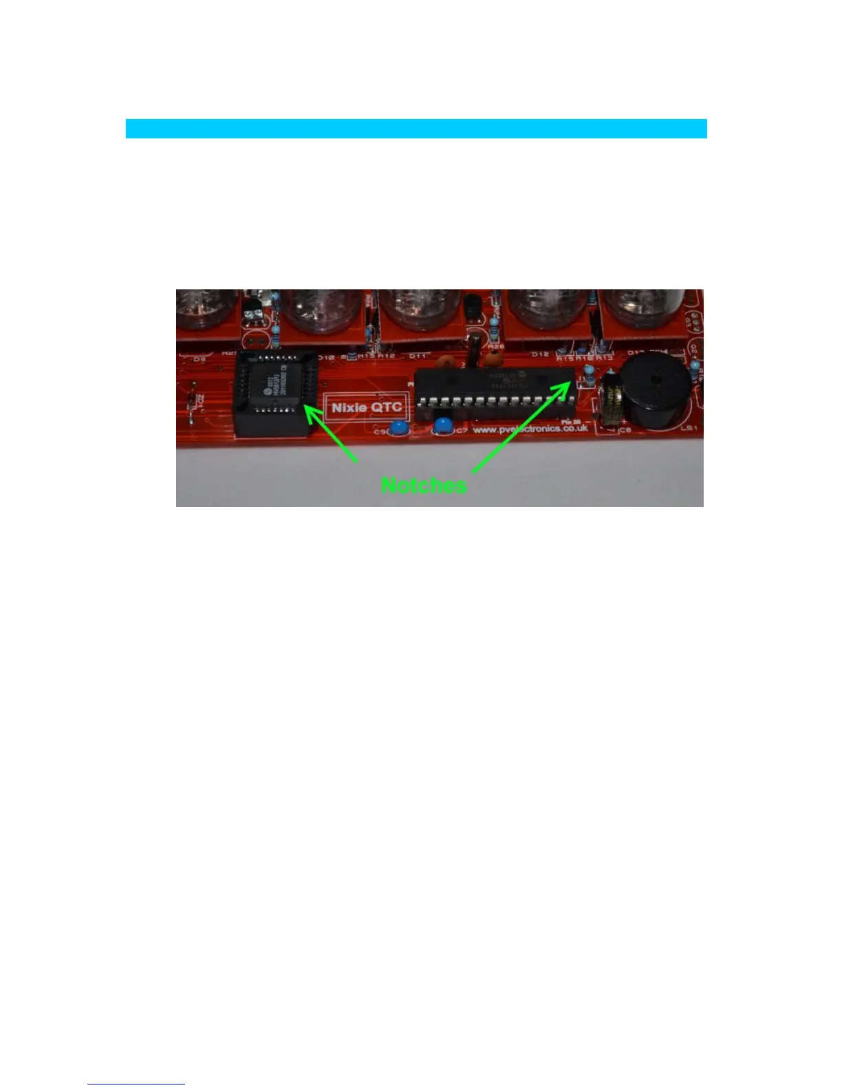
6.1 Insert IC2 and IC3
Insert IC2 and IC3 into their sockets, with the notches aligned as
shown below:
6.2 Microcontroller Code Configuration
The Microcontroller IC2 needs to be setup for your tube type as the
tube connections differ for the 3 types of pinout that the kit
supports. However, most tubes use configuration 'A'. If you are
using a tube which requires configuration 'A', you can omit this
step as the microcontroller is programmed to this configuration as
a factory default. However it is still worth noting the procedure
below, in case for some reason you accidentally change the
configuration you can then change it back.
To change the configuration, be sure the supercapacitor is
discharged. If it is not discharged, leave the clock unplugged for 6
hours to fully discharge it.
Then keep one of the following buttons pressed whilst re-
connecting power. This will reconfigure the controller and the
change will be stored to non- volatile memory.
Configuration A: Press the SET button
Configuration B: Press the ADJ button
Configuration C: Press the ALARM button
After configuring the controller as above you can immediately
power off the clock, and proceed to the first tube tests below.