All the resistors on the board need to be mounted upright to save
space. The leads need to be formed as shown below. Bend the
leads of each resistor as shown and solder in to the correct postion,
making sure the component body is as close to the board as
possible.
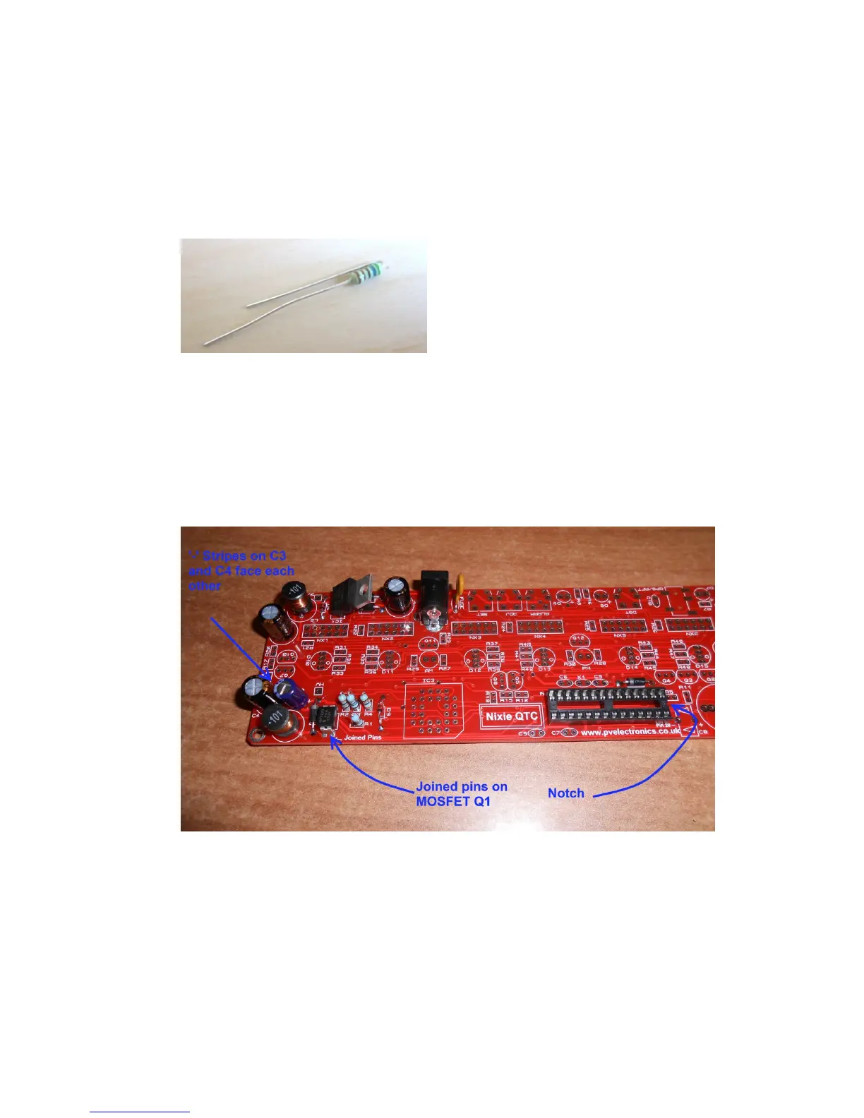
Take care that the notched end of the IC socket is at the end
shown. Also the MOSFET needs to be placed with the two joined
pins at the position shown below.
Ensure that the (-) light stripes on C3 and C4 are facing inwards
towards each other as shown below.