9
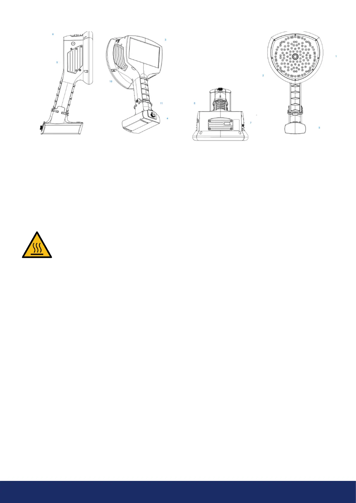
The front side of the LF10 camera consists of a video
image sensor (Item 1 in Image 2) and the microphone
array (Item 2 in Image 2). The camera screen displays
amonochromatic (black and white) image on which the
acoustic colored-coded heatmap is overlayed.
The LF10 camera has a resistive touchscreen (Item 3
in Image 2). Users can operate the screen even when
wearing gloves. Do not apply any sharp or hard objects
touse the screen, as they may damage the surface.
Exerting excessive force will degrade the durability
ofthetouch screen.
The status of the internal power supply unit is indicated
by the power LED (Item 6 in Image 2), which turns red
when the power is ON. While the power is ON, the LF10
dissipates heat through the three heatsinks (Items 8, 9,
and 10 in Image 2) that are located on both sides and on
top of the camera. While operating the LF10, the heat
sinks must be not be covered. Do not enclose the device
while the power is turned ON.
The camera has a USB port located under the cover on top
of the device (Item 7 in Image 2).
Using the wrist lanyard will protect the LF10 from getting
damaged if dropped (Item 11 in Image 2). However, do
not carry the LF10 camera by the wrist lanyard only.
NOTE: Protect the camera lens and microphone array
against coming into contact with any foreign objects,
dust, or liquids.
Image 2: LF10 camera parts
2.4 Camera parts
- NOTE: Refrain from touching the heat sinks (Items 8, 9, and 10 in Image 2 above), as they become
hot during use. Long-term contact may cause burns. -
1: Video camera
2: Microphone array
3: LCD screen
4: Battery cover
5: Battery housing
or battery cable
(with Tracer external battery),
Camera-end connector
6: Power LED
7: Mass storage port
8: Top heatsink
9: Right-side heat sink
10: Le-side heat sink
11: Lanyard fastening point
12: ON/OFF button