24
4.7.3 Hydraulic Plumbing
WARNING!
From this point in the installation the
booms will be inoperative until the
electronics are fully installed.
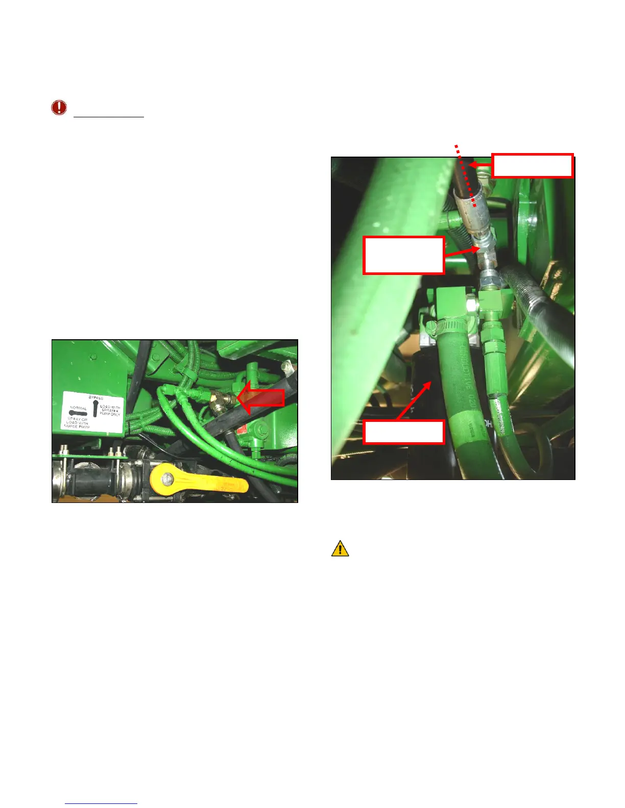
1. After the NORAC valves are mounted, the
hydraulic hoses and fittings can be plumbed.
The plumbing for the hydraulic circuit is
shown schematically in Figure 3.
2. Tee hose H70 into the port on the priority
valve labeled EF. This is located on the left
hand side, under the rear corner of the cab
outside the frame. Use the 12FORXOR-
12MORT Tee fitting (F11) (Figure 32).
Figure 32 - Secondary Pressure Line
(H70) (teed into the priority valve EF
port)
3. Route hose H70 to the NORAC valve
block, following existing hoses.
4. Attach the 6FORXR-6MORT tee fittings
(F10) to the P and T ports on the NORAC
Valve block.
5. Attach hose (H70) to the 6FORXR-6MORT
tee fitting (F10) in the P port on the
NORAC valve block.
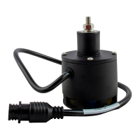
6. Tee hose H71 into the inlet on the sprayer’s
hydraulic in-line filter using a 6FORXR-
6MORT tee fitting (F10). (Figure 33)
Figure 33 - Secondary Tank Line (H71)
(teed into the tank return near the in-line
filter)
The load-sense return line (also teed
into the in-line filter) has an orifice
between the fittings. Ensure the
orifice is located in a manner that it
will not restrict the flow of the new
tank line (H71). In Figure 34,
illustration A shows the original
plumbing of the load sense return and
orifice. B and C show two options for
installation of the tee fitting.
Tee Fittin
F10
Hose H71
In-line Filte