WWW.NORAC.CA
PRECISIONDEFINED
Page10
Visitwww.solutions.norac.caformoresystem
installationandtroubleshootinginfo.
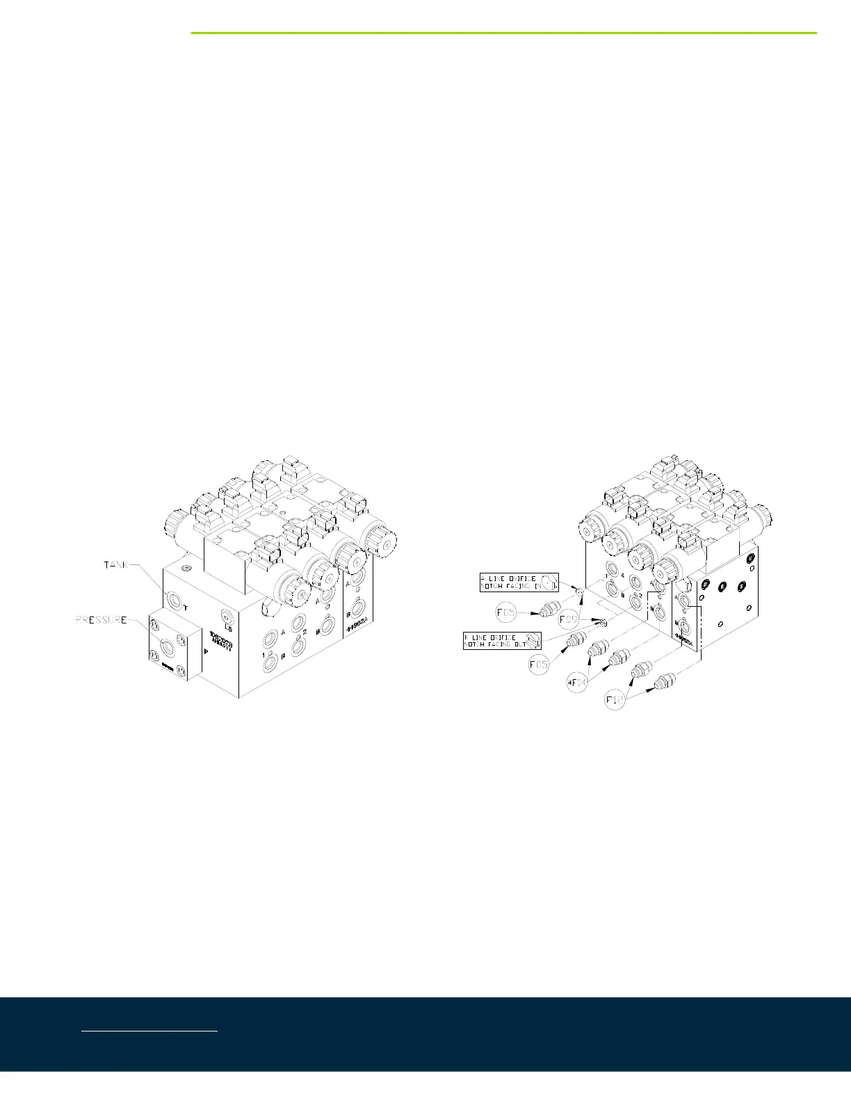
5.2. ValveBlockAssembly
1. Onacleansurfaceremovetheplasticplugsfromtheblock.
2. Installthe6MB‐6MJ(F02)fittingsintothe“P”and“T”ports.Tightento18ft‐lbs(24Nm).
3. Insertthetwo(2)orifices(F09)intothe“B”portswiththenotchfacingoutward.
4. Installthe
6MB‐6MOR(F05)fittingsintothe“B”ports.Tightento18ft‐lbs(24Nm).
5. Insertthetwo(2)orifices(F09)intothe“A”portswiththenotchfacinginward.
6. Installthe6MB‐6MOR(F05)fittingsintothe“A”ports.Tightento18ft‐lbs(24Nm).
7.
Installthe6MB‐6MORfittings(*F04)intothe“A”and“B”portsofthe3
rd
station.
8. Installthe6MB‐6MOR(F12)fittingsintothe“A ”and“B”portsoftheexpansionblock.Tightento18ft‐
lbs(24Nm).
Figure5:NORACValveBlockDetails