WWW.NORAC.CA
PRECISIONDEFINED
Page24
Visitwww.solutions.norac.caformoresystem
installationandtroubleshootinginfo.
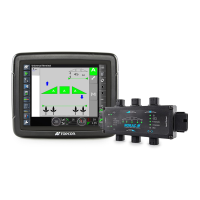
Figure25:CablesUnderMountingClips(SideView)
Figure26:CablesLaidAcrossValveCoils(TopView)
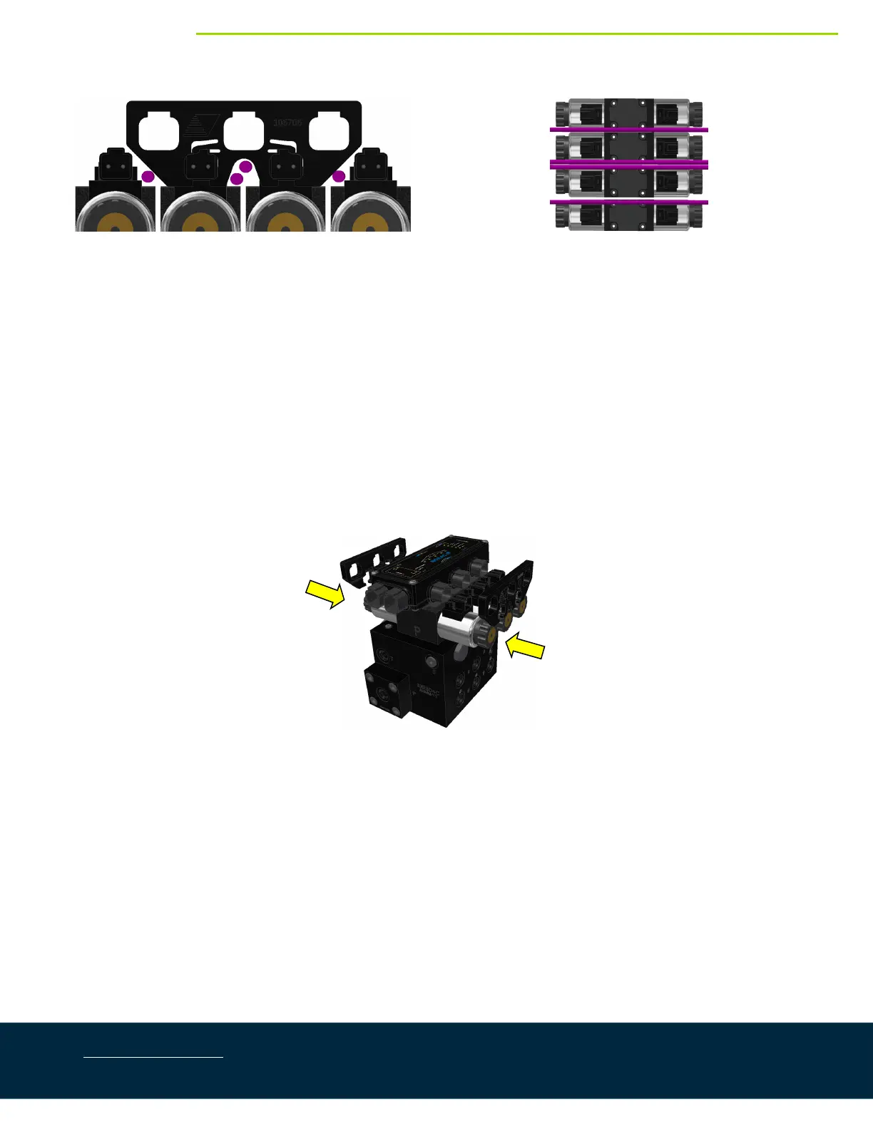
3. Place the HCM1(E01) between thevalve coils.Orientthe6‐pin Deutsch (CANbus)connectorstowards
the“P”and“T”portswiththelargelabelandLEDsfacingup.
4. Slide the mounting clips over the connectors of the HCM1 and the valve coil connectors.This may
requireflexingthe
plasticbracketslightly.Ensure the clipispushedover the connectorsfarenough to
allowtheclipstoengagebehindthevalveconnectors.
5. Connect the valve cables (C10) to the valve coils and the HCM1.The cable connected to the left
connector(1,2)shouldbeconnectedtothecoil
closesttothe“P”and“T”ports.Thecableconnectedto
the right connector on the HCM1 (3,4) should be connected to the coil furthest from the “P” and “T”
ports.Thecableconnectedtothe mainliftconnector (5,6)shouldbe connectedtothe 3
rd
stationcoil.
Thecableconnectedtotherollconnector(7,8)shouldbeconnectedtothecoilontheexpansionblock.
Figure27:HCM1andClipInstallation
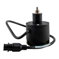
6. Connectthetemperatureprobe(C11)totheHCM1(temp/9connector).Connectthetemperatureprobe
tothehole l abelled“TP”onthevalveblockusingthesupplied3/8”x1/2”(9.5mmx25mm)bolt(Figure
28).
7. Insert4‐pinplugs(P01)intoanyunusedconnectorsontheHCM1.