WWW.NORAC.CA
PRECISIONDEFINED
Page25
Visitwww.solutions.norac.caformoresystem
installationandtroubleshootinginfo.
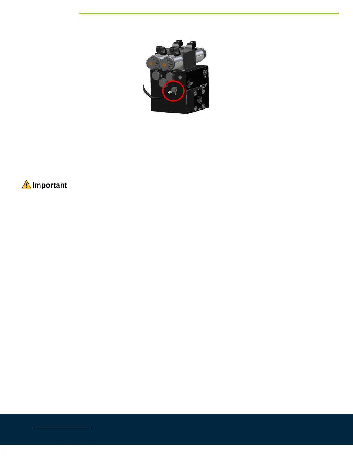
Figure28:ValveBlockwithTemperatureProbeInstalled
8. Connectthe12‐pinconnectoroncableC20totheHCM1.Teetheconnectorsontheshorterbranchof
cableC20intotheleftup,leftdown,rightup,andrightdownfunctions.
9. Tee the connectors on the longer branch of C20 into the main up and main down functions on the
sprayervalveblock.Themainliftvalveislocatedonthebellyofthesprayer,forwardoftherearaxle.
Ensurethatallunusedconnectorsarepluggedwiththeplugsprovided.