10.4.3 User Manual Contents April 17, 2020
Firmware: 5.2.1 Page 113 of 142
A sensor in use requires the real-
time heave calculated at its position
on the vessel and I am using NTRIP
for RTK correctors
Follow the above steps for setting up the POS MV and set NTRIP
service to a static position and input a position preferably located in
the center of the survey area.
I have a GPS receiver tied to my
satellite corrector subscription
service and need to bring it into the
POS MV on the WBMS.
Under Lever Arms & Mounting Angles > Sensor Mounting, enter
the XYZ offsets to the auxiliary GPS receiver under the Ref to Aux 1
GPS. Under Input & Output Configure COM 3 Input to AUX 1 GPS.
This allows the POS MV to base its positions off the more accurate
position obtained from the auxiliary GPS receiver
Running Installation Calibration Control
When offset measurements from the IMU sensing center to antenna phase center is not accurately
measured or difficult to measure due to long measurement runs and around many bulkheads then
it is possible to automatically calculate these offsets using POSView. This requires clear views to at
least 6 GNSS satellites that are positioned in different orthogonal quadrants with at least one satellite
(nearly) directly overhead and a strong RTK Fix positioning solution. Enter in the best measured
offsets (determined from a mean of multiple calibrations) to the “Reference to Primary Antenna” in
the Lever Arms window.
CAUTION: Installation Calibration Control Is Not Reliable
Use of the Installation Calibration Control routine should only be used if
physical offset measurements cannot be performed. The routine should be
run a minimum of 3 times and values averaged.
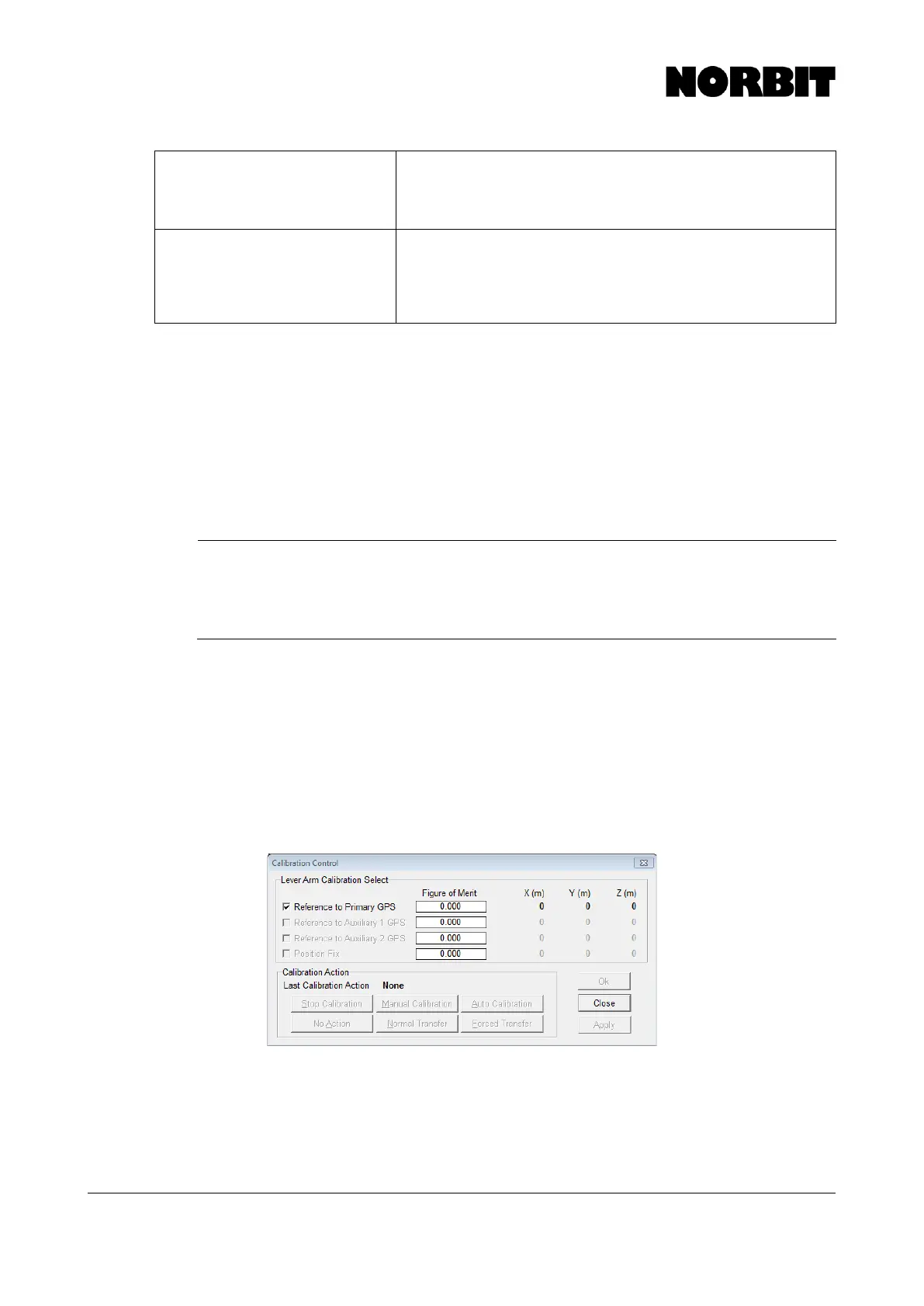
Go to Settings > Installation > Installation Calibration Control. This opens the dialogue window
shown below. Select Reference to Primary GPS, then select Auto Calibration and OK.
Immediately begin moving the vessel through tight figure-of-eight motions. The Figure of Merit will
begin to count to 100 as solutions are determined. When complete, record the newly derived offsets
on paper and run again. When the values remain steady to within 1cm, select Normal Transfer to
copy these values to the Ref. To Primary GPS Lever Arm. Select Save Settings in the Settings
pull-down. If the reference location in the POS MV is chosen to be a point other that the sensing
center of the IMU, then apply the additional offsets to the derived values. Following this procedure,
run a GAMS calibration.
Applanix POS MV Nav Status
Applanix POS MV v8.63 incorporates the following navigation status types. The Nav Status displays
the source and quality of the GNSS sensors and the resulting mode of the navigation solution. These
are listed below with those highlighted in green being the best solutions: