10.4.3 User Manual Contents April 17, 2020
Firmware: 5.2.1 Page 112 of 142
Appendix B:
Advanced Applanix Setup
While NORBIT has integrated many features of the Applanix into the NORBIT GUI, some features
were not included to keep operation clean and simple. The features not included are typically used
by a small subset of NORBIT users. If you require a feature that is not found inside the NORBIT GUI
you may have to utilize POSView. If an item is not found within this section, please refer to the
Applanix user guide.
POSView can be used in conjunction with the NORBIT GUI. However, during INS setup in the
NORBIT GUI, POSView must be in the monitor state and not in the connected state.
CAUTION: Use Correct POSView Version
Do not use a POSView version that is incompatible with POS firmware
installed on the sonar system. Doing so can cause unexpected errors in the
POS MV system.
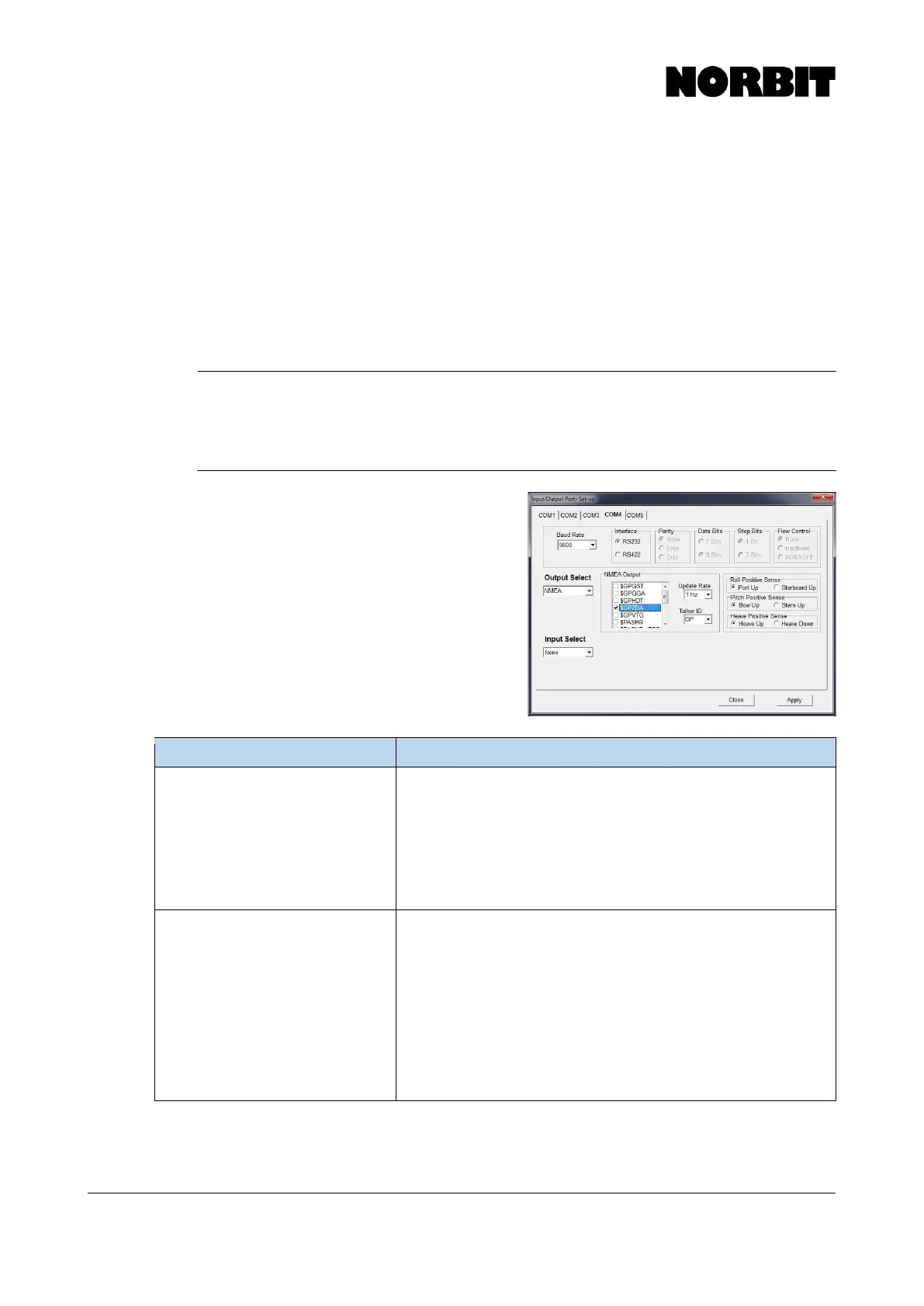
Alternate COM port setup
Some scenarios may require an alternate setup of
the POS MV Com ports. Refer to the table below for
guidance on handling some of these special
scenarios. If a desired setting is not shown in the
table below, contact NORBIT support for assistance.
A sensor in use requires heading in
NMEA format. I am using an NTRIP
service that required GPGGA
Obtain a DB9 Y splitter.
Set COM 3 to output a GPGGA string required by NTRIP and select
a GPHDT string required by the device. Set the baud rate and the
update rate to a setting required by the device.
Use one side of the Y splitter to connect to the computer for NTRIP
and connect the other end to device.
*If the baud rate is set high enough there should be no issue in
outputting any number of NEMA strings from the iWBMS
A sensor in use requires the real-
time heave calculated at its position
on the vessel and I am using base
station broadcasting RTK correctors.
Under, Lever Arms & Mounting Angles > Sensor Mounting, enter
the XYZ offsets to the sensor in question.
Under the COM 3 output select Binary and select the message string,
and the device update rate. To the right of the update rate select
Sensor 2.
Under input, select Base 1 and select the type of correctors being
used.
Use a Y splitter to bring RTK corrections into the SIU and the Binary
message to the desired device. In some applications a Null modem
may be needed.