10.4.3 User Manual Contents April 17, 2020
Firmware: 5.2.1 Page 30 of 142
3.1
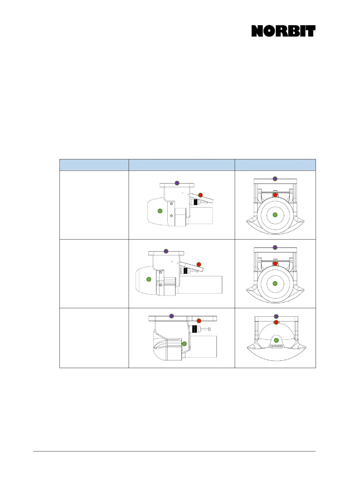
Reference Points
In the drawings below, the WBMS Reference Point (red dot) is where all sonar and navigation data
are valid by default. This point is located at the center of the projector in the fore-aft direction, and
at the center of the cylindrical receiver array in the port-starboard and vertical directions.
The green dot indicates the IMU Reference Point. Generally, the user need not concern themselves
with the IMU reference point, unless the IMU is physically decoupled from the sonar.
The purple dot indicates the Top Center of Bracket. This is merely a convenient point from which
to measure the primary GNSS antenna offset, as the WBMS and IMU reference points are not
necessarily physical points that can be directly measured.
Refer to section 3.2 for all relevant offsets and mounting angles for each WBMS configuration.