Appendix A:
Quick Start Guide
Users are advised to refer to this section for a quick, basic installation guide without detailed
descriptions of each operation. NORBIT recommends that users familiarize themselves with detailed
descriptions of each operation/function before using this guide.
WBMS sonar-only users should skip sections related to INS configurations.
1. Unpack and Inspect: Unpack sonar system and inspect all cables and connectors for
damage, dirt and moisture. Inspect the sonar for especially around the transducers for
cuts or gouges.
2. Sonar Installation: Depending on vessel being used, make an installation plan. Follow
this plan to mount sonar (ideally with NORBIT bracket) on the vessel and align unit to be
parallel with the vessel keel with the projector pointing aft. Bolt sonar bracket to pole with
minimum of 4 bolts. Use lock-washers and/or LOC-TITE especially for longer duration
setups as nuts will vibrate and loosen over time. Users are advised to connect wet-end
sonar and IMU cables before mounting the system. This simplify the process of securing
cables.
3. Antennas: For GNSS/INS integrated WBMS: Mount GNSS antennas with 5/8” threaded
bolts. While not necessary, it is helpful to align GNSS antennas to be parallel or
perpendicular to vessel keel. The antenna closest to the WBMS is the primary. Select an
antenna cable, label it at both ends (to prevent confusion) and use this to connect primary
antenna to Ant1 on the SIU. Connect the secondary antenna to Ant2.
4. Cables: Run cables from sonar and antennas to SIU. Avoid sharp bends and be cautious
of chafing. Handle cables with care – rough handling will bend connector pins in the cables
and lead to loss of signal. Do not run cables next to high voltage lines – spread cable out
to avoid RF interference.
5. SIU & PC: Connect the SIU to the control and acquisition PC via ethernet. Before
powering the sonar set the IP address of the PC to 192.168.53.XXX where XXX can be
any number from 101 to 255; set the subnet mask to 255.255.255.0
6. RTK: If RTK is being used, set it up as needed.
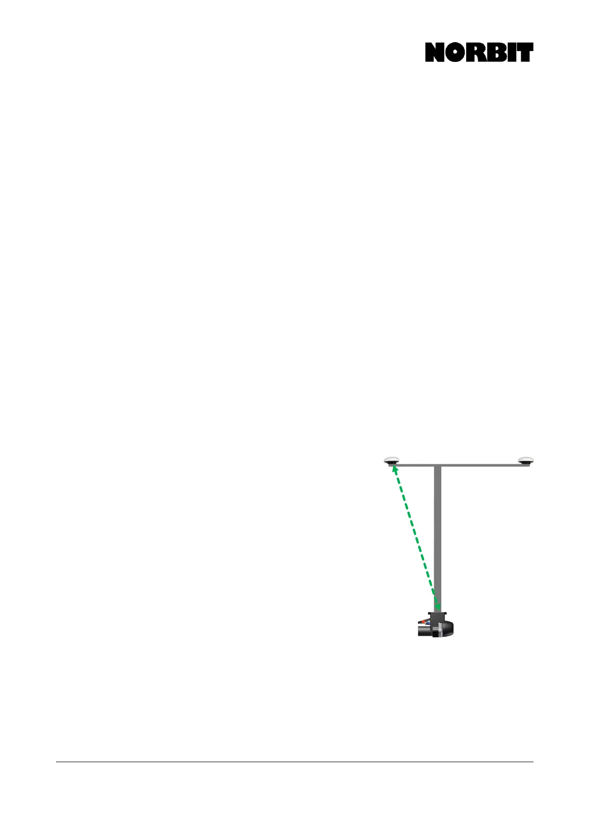
7. Offsets: For the default setup, measure offsets
(green dotted line in image) from Top Center of
Bracket to base of primary antenna (the antenna
closest to the WBMS Reference Point).
8. Power: Ensure power source is clean. Be aware of
batteries that are under powered or cheap inverters.
9. Software: On the control and acquisition PC, install
the WBMS GUI version 10.4.0. For iWBMSc users,
also install NovAtel Connect. With all hardware
connected to the SIU, power it on and open WBMS
10.4.0. On the Connection State tab wait until the
Control Line, Firmware and Sonar Log turns green.
Then click on Connection Dialog and select the
correctly detected sonar and click Connect. Once
connected, the GUI should start logging GNSS/IMU
data automatically.
10. INS Setup: In the GUI, navigate to INS Tools in the
settings menu and open INS Setup Wizard. For the default and recommended setup,
simply follow the prompts in the setup wizard and have the measured offsets, from top
center of bracket to base of primary antenna, at hand. For the baseline vector, select
Alignment Wizard. This way, the wizard will open automatically once the setup wizard is
complete. The Alignment Wizard was known as the GAMS calibration in POSView. This
process ensures agreement in the heading alignment between the GNSS and INS. For
NovAtel users please refer to the NovAtel Setup information section of this manual for
setup instructions.