In the decoupled mounting configuration, offsets from the IMU/CoR to WBMS Reference Point must
be applied in the chosen acquisition software. If the
IMU is at not the CoR/vessel reference point, the IMU
offsets also must be measured and applied in the
acquisition program.
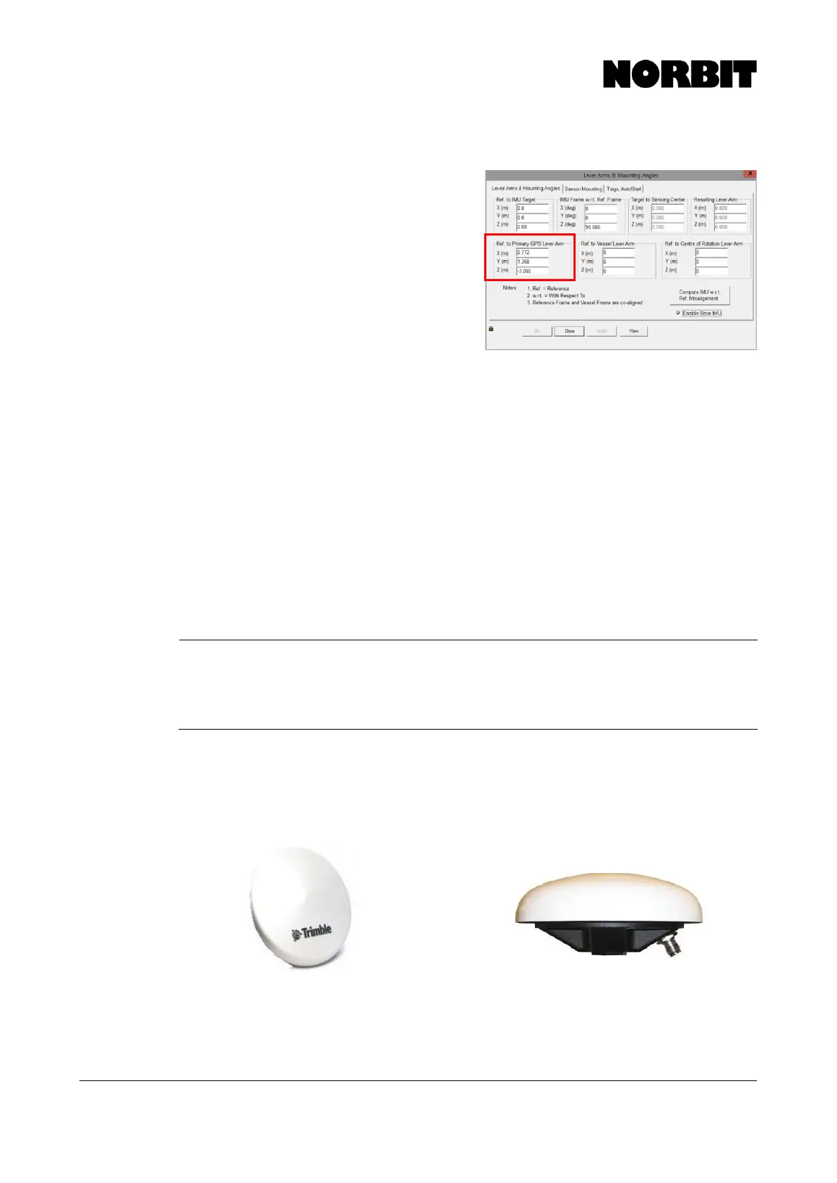
In the decoupled mounting configuration, the IMU
offset should be measured from the vessel CoR to the
center of the IMU fairing. The sensing center of the
IMU is 0.08m below the top of the fairing. This value
should be entered in Ref. to IMU Target. Offsets
highlighted in red must be entered based on vessel
offsets.
Two cables are required if operating the system in a decoupled configuration: the standard split
cable for the IMU and a separate WBMS cable for the sonar.
For further information and assistance with this, please contact NORBIT support. Once POS starts
receiving the Marinestar signal, the Nav Status will change to “Pri. Marinestar GPS” on the main
POS MV display.
Ref to Center of Rotation Lever Arm
During surveys where RTK or PPK are not/cannot be utilized then the offset from WBMS Reference
Point to vessel center of rotation should be entered to the Applanix POS MV. Applying these offset
aids, the Applanix in properly computing both real-time heave as well as delayed heave. Extreme
care must be taken when entering in these offsets as there is no way to correct incorrect offsets in
post-processing. Failure to accurately enter the offsets results in incorrect heave calculation and
degrades data quality.