Prior to installation, always inspect cables for nicks and sheath wear. If there are any hazards that
may expose cables to abrasion, it is advised that a chafing guard to protect the cable be made such
as adding rubber tape around the cable at the point of concern. Ensure pins are not bent and that
they are shiny for robust connectivity.
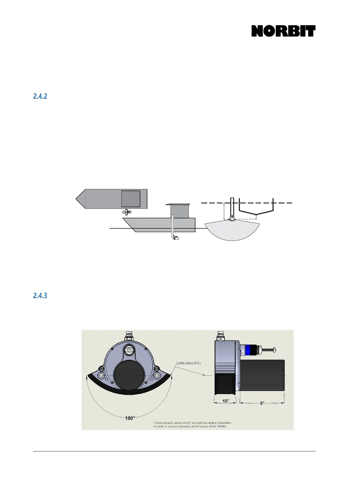
Sonar Mounting Location
Generally, the WBMS Reference Point should be clear of the lowest part of the hull, at the mounting
location. This is to avoid reflections from hull and water surface. A strong hull-reflection will reduce
SNR for all beams (simply rotating the wedge in software will not blank out a strong reflection).
Additional sonar draft may be required depending on the characteristics of the vessel hull which may
create bubbles during vessel motion, especially as sea state worsens. It is critical that the sound
speed sensor on the WBMS has clean bubble-free water.
Mount the sonar in a location that will minimize interference from engine noise and the effect of
vessel motion on data quality; for most vessels, this location is approximately down 3/4 the length
of the hull on the port or starboard side. In certain cases, the sonar can be successfully mounted
near the outboard motors, e.g. on the transom of a 2.5m inflatable boat.
While the antennas may be oriented in any direction horizontally, it is good practice to orient them
to be parallel or perpendicular to the vessel centerline.
Label the Antenna1 cable at both ends before installation to identify which of the two cables is the
Primary when connecting to the SIU.
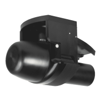
Acoustic Clearance Zones
In shallow water conditions, when danger of collision with sonar is especially high, users may want
to build a safety cage around the sonar. The image below indicates areas that must be kept clear to
receive a clean signal.