DRAFT
NOT FOR PUBLIC RELEASE
19
www.norcold.com/cda N500/N510 ModelsRefrigerator Service Manual
Before beginning this procedure:
■
Make sure thermistor assembly is connected to the wire harness.
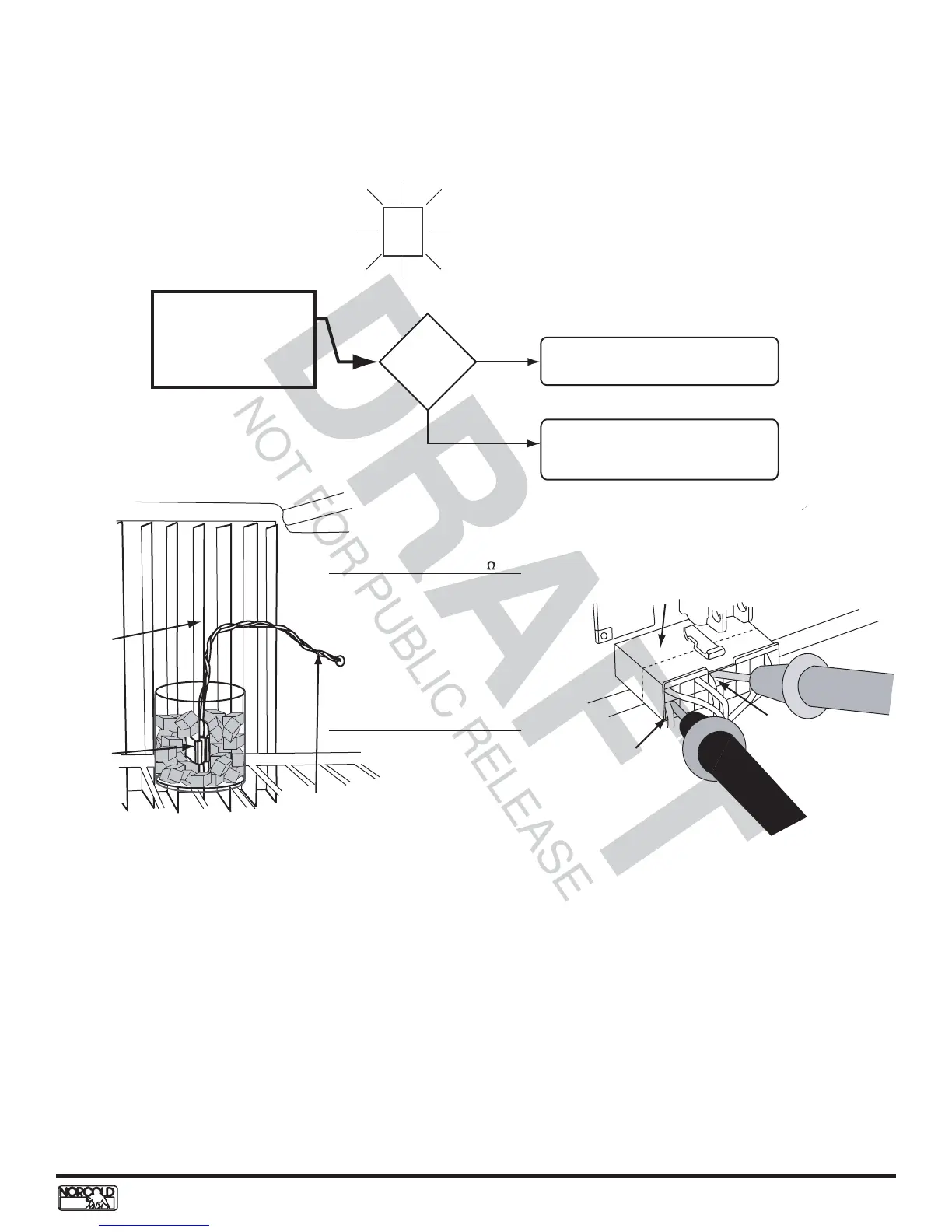
Fault indicator displayed:
Clean/repair terminals or connector as
required.
NO
Check thermistor resistance. See Figures
10 and 11. If resistance is not within
specified ranges, replace thermistor.
Wires and
connector
good?
Check thermistor wire
assembly and connector for
dirty/broken connections.
Thermistor connectors are
located in P1 connector
terminals 8 and 13.
YES
LP GASAC
AUTO
Temp
Setting
Flashing
Thermistor Failure Fault - Controls in Backup Operating System Mode - N510
Figure 10. Thermistor assembly
Figure 11. Checking thermistor resistance
Backup Operating System - N510 Models
The backup operating system (BOS) is an electronically
controlled duty cycle. It maintains the refrigerator in
operation if the thermistor is disconnected or fails. The
BOS maintains cooling by controlling the heat source
selected. When the refrigerator is operating in BOS, the
length of the cooling cycle is regulated not by
temperature, but by time.
To accomplish this, the BOS adjusts the length of the
cooling cycle according to the temperature setting
selected by the user--the higher the temperature setting,
the longer the cooling cycle. For example, if the
temperature setting is set to 4, raising the setting to 5
will lengthen the cooling cycle, making the cabinet
colder.
When a warmer temperature is desired, changing the
temperature setting to a lower number shortens the
cooling cycle. For example, if the temperature setting is
set to 5, lowering the setting to 4 will shorten the cooling
cycle.
When the N510 controls shift to BOS operation, the
temperature setting flashes for ten seconds when the
TEMP button is pressed. After ten seconds, the selected
operation mode indicator displays.
Pin 13
Pin 8
16 pin connector
Thermistor
packed in
ice bath
Thermistor wiring
(to 16 pin connector)
5th Fin
Temperature* Resistance*
(
o
F) (k )
85 8.1– 9.0
80 9.1–10.0
75 10.1–11.0
70 11.1–12.0
60 12.1–13.0
50 15.5–16.5
40 22.5–23.5
35 24.5–25.5
33 28.5–29.5
32 30.0–32.0
*
Approximate Values