DRAFT
NOT FOR PUBLIC RELEASE
47
www.norcold.com/cda N500/N510 ModelsRefrigerator Service Manual
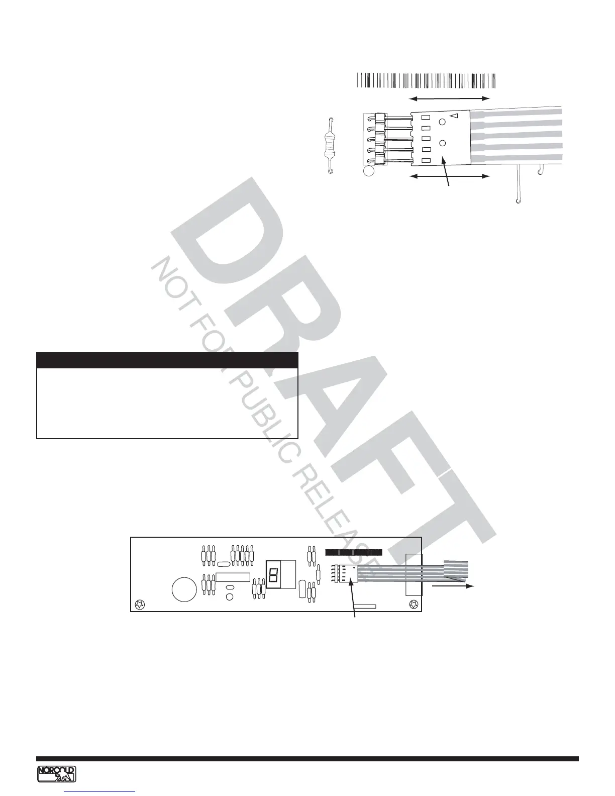
Figure 43. Optical display circuit board
1000-00 620000
1234
DB123456NO123456
Display overlay
ribbon connector
To display
overlay
15. Install optical control circuit board then install the
board retaining screws.
16. Install the board bracket retaining screws (2).
17. Reconnect wire harness.
18. Install refrigerator in enclosure.
Replacing Optical Control Circuit Board - N510
1. Turn OFF refrigerator.
2. Unplug ac power cord.
3. Disconnect 12 Vdc supply.
4. Disconnect LP gas supply.
5. Remove screws from back mounting flange (if
present).
6. Remove retaining screws located on the front of
breaker (will need to open door to remove).
7. Remove refrigerator from enclosure.
8. Disconnect wire harness.
9. Remove the board bracket retaining screws (2).
10. Remove board retaining screws, then remove
optical control circuit board.
11. Disconnect display overlay ribbon connector from
optical control circuit board. See Figure 42 and
Figure 43.
12. Remove metal brackets from circuit board.
13. Transfer brackets onto new optical control circuit
board.
14. Connect display overlay ribbon connector to optical
control circuit board. See Figure 42.
P2
R14
DB4003NO12345
Display overlay
ribbon connector
Figure 42. Connecting/disconnecting connector
When connecting the display overlay ribbon connector
to the circuit board, be sure to keep the flat side of the
connector against the board and the side with the arrow
visible. If this connector is installed incorrectly, the
refrigerator will not turn on.
NOTE
19. Install breaker retaining screws.
20. Install back mounting flange screws, if present.
21. Reconnect dc power supply.
22. Plug in ac power cord.
23. Place refrigerator in service.