DRAFT
NOT FOR PUBLIC RELEASE
42
www.norcold.com/cda
N500/N510 Models
Refrigerator Service Manual
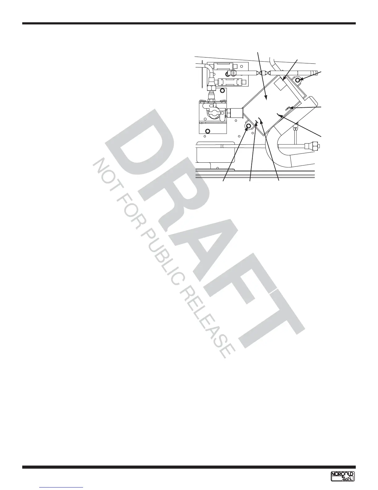
Figure 37. Relighter and connections
Relighter - N500 Models
The relighter relays signals from the gas safety valve to
the spark/sense electrode and to the flame indicator. It
operates on 12 Vdc. See Figure 37.
Replacing Relighter
Refer to Figure 37 for component locations.
1. Turn OFF refrigerator.
2. Unplug ac power cord
3. Disconnect RV 12 Vdc supply at terminal block.
4. Close manual shutoff to LP gas supply.
5. Disconnect orange spark/sense electrode wire.
6. Disconnect 12 Vdc from relighter.
7. Disconnect ground wire.
8. Disconnect flame indicator wire.
9. Disconnect selector switch wire.
10. Remove retaining screws (2).
11. Install replacement relighter.
12. Install retaining screws (2).
13. Reconnect selector switch wire.
14. Reconnect flame indicator wire.
15. Reconnect ground wire.
16. Reconnect 12 Vdc to relighter.
17. Reconnect spark/sense electrode wire.
18. Open LP gas manual shutoff.
19. Reconnect RV 12 Vdc supply at terminal block.
20. Plug in ac power cord.
21. Place refrigerator in service.
Relighter
Spark/sense
electrode
(orange)
DC powe
supply
(white)
Ground
(green)
Selector
switch
(black)
Flame
indicator
(red)
Retaining
screw
Retaining
screw
Flame Indicator - N500 Models
The flame indicator allows the user to monitor the LP
gas flame when the refrigerator is in LP Mode. The
flame indicator lights indicates the existence of a flame
through the relighter.
Flame Indicator Replacement
1. Turn OFF refrigerator.
2. Unplug ac power cord.
3. Disconnect 12 Vdc supply.
4. Disconnect LP gas supply.
5. Remove screws from back mounting flange (if
present).
6. Remove retaining screws located on the front of
breaker (will need to open door to remove).
7. Remove refrigerator from enclosure.
8. Remove wiring shroud (four screws).
9. Disconnect black indicator wire from power supply.
10. Disconnect red indicator wire from relighter.
11. Remove flame indicator.
12. Install replacement flame indicator through the front
of the control panel until it clicks into place.
13. Reconnect red and black flame indicator wires.
14. Replace wiring shroud.
15. Install refrigerator in enclosure.
16. Install front breaker retaining screws.
17. Install back mounting flange screws.
18. Disconnect LP gas supply.
19. Reconnect 12 Vdc power supply.
20. Plug in ac power cord.
21. Place refrigerator in service.
ELECTRONIC COMPONENTS - N500 MODELS