NORD USS and Modbus RTU Manual
14 Subject to technical amendments BU 0050 GB-3111
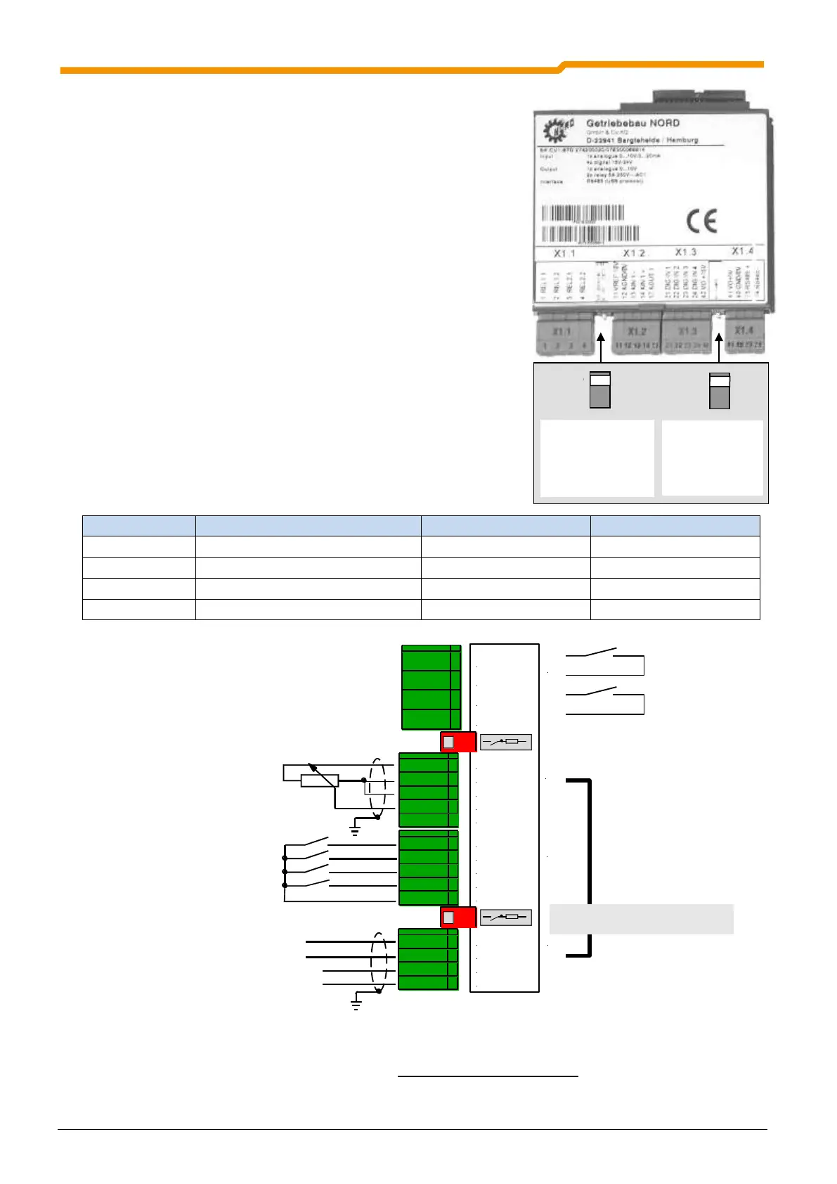
1.2.2.4 Customer unit Standard I/O
(SK CU1-STD, Option)
The standard I/O of the customer interface(Customer Unit) provides
sufficient control terminals for most applications and it is fully
terminal-compatible with NORDAC vector mc..
1 analog differential input, 4 digital inputs and 1 analog output are
available for control of the frequency inverter.
Readiness for operation is shown via the 2 relay contacts and a
mechanical motor brake is activated at the correct time.
The connected frequency inverter can be accessed via the RS485
interface. In addition to the entire range of control functions,
parameterisation is also possible.
TheNORD CON software can be used to carry out a simple function
test of the serial interface and the parameterisation of the inverter.
For this, an interface converter (e.g. SK IC1-232/485) must be used
between the PC and the inverter. Following successful
parameterisation, the complete data set can be stored as a file by
means of NORD CON.
Bus signals / power supply
74 RS485 -
X1.1
X1.2
X1.3
X1.4
11 VREF 10V
12 AGND /0V
13 AIN1 -
14 AIN1 +
17 AOUT1
21 DIG IN 1
22 DIG IN 2
23 DIG IN 3
24 DIG IN 4
42 VO +15V
41 VO +5V
40 GND /0V
73 RS485 +
01 REL1.1
02 REL1.2
03 REL2.1
04 REL2.2
NOTE: All control voltages are based on a common reference potential!
Potentials AGND /0V and GND /0V are internally linked in the device.
The maximum total current 5/15V is 300mA!
Potentialfreier Kontakt oder
Ausgang einer SPS: 7,5...33V
(low = 0...3,5Volt)
Differenzeingang 0...10V
0...20mA
Voltage supply: 5V
RS 485 (USS protocol)
5V supply for ParameterBox,
p-box or motor thermistor
Data cables USS protocol
Digitale Eingänge:
DIG IN 1 = Ein rechts
DIG IN 2 = Ein links
DIG IN 3 = Parametersatz bit 0
DIG IN 4 = Festfrequenz 1
Ausgangsrelais:
max. 2,0A
28V DC /230V AC
U
REF
= 10V / I
max
= 10 mA
Analogausgang SPS: 0...10V
oder Potentiometer: 2...10k
Termination resistor for
RS 485 interface (120)
Zuschaltbarer Bürdenwiderstand für
0/4...20mA Analogeingang (250)
U/I switching
Analog input,
250
ON = Current,
OFF = Voltage
Termination
resistor
RS 485
120
 Loading...


