NORD USS and Modbus RTU Manual
16 Subject to technical amendments BU 0050 GB-3111
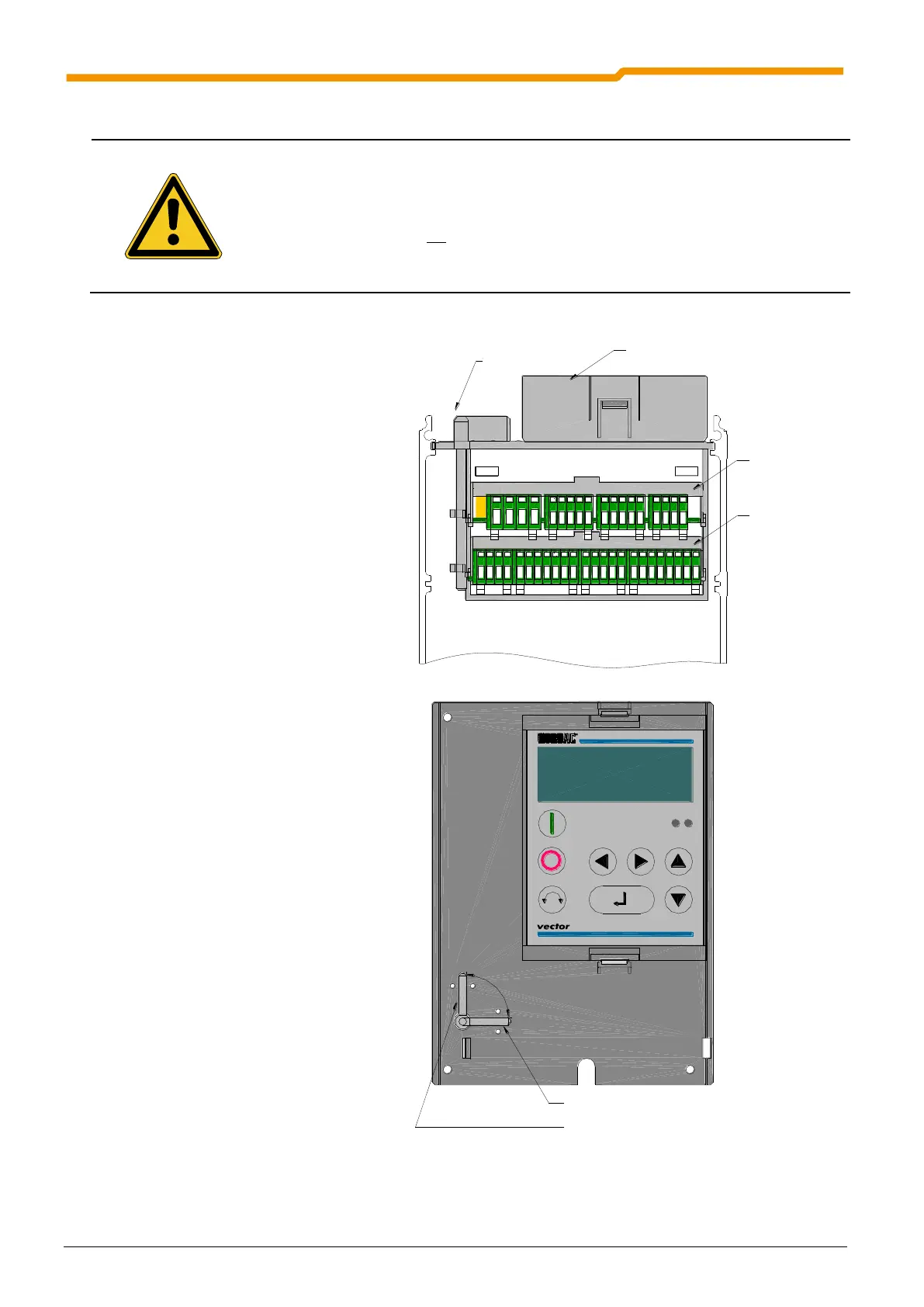
1.2.2.6 Installation of customer units
Installation must be carried out by qualified personnel only, paying particular
attention to safety and warning instructions.
A customer interface must not be replaced while it is carrying voltage.
1. Switch off the mains voltage, observe
the waiting period.
2. Remove the cover grid from the
connection area by loosening the 2
screws and levering out the device cover
(slot) or simply pull it out.
3. Locking lever in the "open" position.
4. Using light pressure push the customer
unit into the upper guide rail until it
engages.
5. Move the locking lever to the "closed"
position.
6. Remove the connector by pressing the
releases then make the necessary
connections. Then insert the connectors
until they engage.
7. Replace all covers.
Kundenschnittstelle
Sondererweiterung
Technologiebox
Verrieglungsstift
CLOSED
OPEN
Verriegelung geschlossen
Verriegelung geöffnet
 Loading...


