4
Installation Instructions for Series 3100V Level Switch
E 2000 Nordson Corporation
All rights reserved
321 355A
Issued 5/00
41--3000--IS--65
Follow this procedure to install the low-level switch.
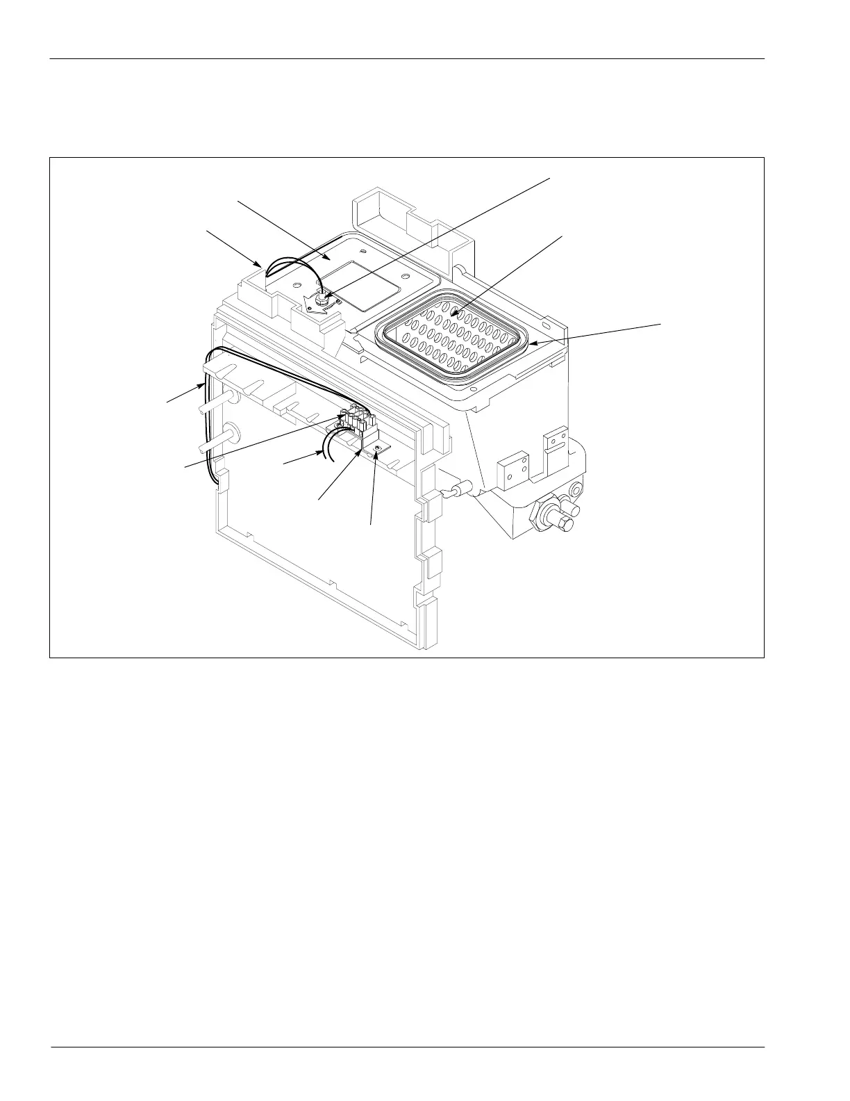
1. Install the new pump pan and low-level switch. See Figure 3.
4131106A
3
1
3
9
7
2
6
5
4
8
Fig. 3 Installed Low-level Switch and Parts
1. Float
2. Tank barrier
3. Wire leads
4. Self-tapping screw
5. Terminal block bracket
6. Terminal block, 4 station
7. Pump pan
8. Gasket, tank cover
9. Customer external device wires
2. Reinstall the pump and reconnect the air supply.
a
g
he Lo
eve
Switch
 Loading...


