17
NOTES:
FIELD WIRING
LEGEND:
LOW VOLTAGE
HIGH VOLTAGE
208/230V
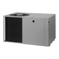
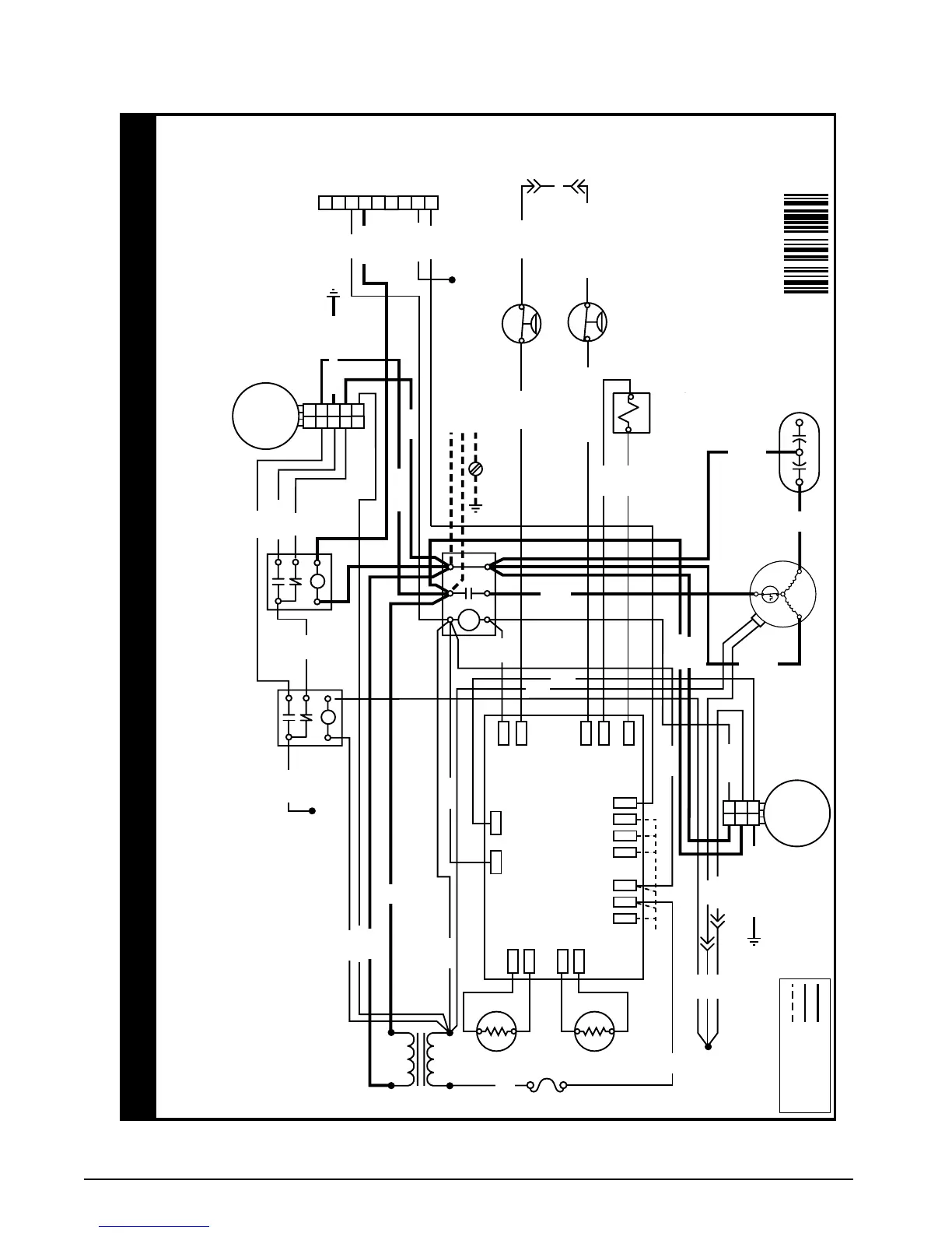
Q5RF/PPH2RF-KA SERIES SMALL PACKAGE H/P W/DEMAND
DEFROST 4 TON AND 5 TON
60HZ/SINGLE PHASE
1. Disconnect all power before servicing.
2. For supply connections use copper conductors only.
3. Not sutiable on systems that exceed 150V to ground.
4. For replacement wires use conductors suitable for 105°C.
5. Unit requires a two stage cooling/heating thermostat
which uses “G” to call for blower.
1. Couper le courant avant de faire letretine.
2. Employez uniquement des conducteurs en cuiver.
3. Ne convient pas aux installations de plus de 150V a la terre.
WIRING DIAGRAM
7112660
0712
L2
L1
T2
T1
4
3
2
1
8
7
6
5
9
LR
C
O
W2
IN
W2
OUT
DF1
AMBIENT
AMBG
COILG
COIL
DEMAND
DEFROST CONTROL
BOARD
REV
VALV E
Y
SW
PRESS
M
C
H
F
DAUL
CAPACITOR
COMPRESSOR
TRASFORMER
240V
24V
HIGH SPEED
BLOWER RELAY
(24V)
BLOWER
RELAY
COM
RED
BLACK
BLACK
BROWN
COMPRESSOR
CONTACTOR
TO T-STAT
BLUE
DF2
YELLOW
WHITE
YELLOW/GREEN
REVERSING VALV E
COIL
BLACK
BLACK
YELLOW / BLACK
YELLOW
YELLOW / BLACK
BLUE
BLUE
YELLOW
YELLOW
5
4
3
2
1
N
G
L
C
BLOWER
MOTOR
1
2
3
L
N
G
OUTDOOR
MOTOR
TO POWER SUPPLY
GND
C
SR
BROWN
YELLOW
ORANGE
BROWN
BLUE
ORANGE
GREY
GREY
GREEN
BLACK
WHITE
RED
YELLOW
RED
RED
BLACK
YELLOW
BLUE
BLACK
BLACK
BLACK
3 AMP FUSE
TO “W3” ON
T- STAT
TO “G” ON
T- STAT
AMBIENT
THERMISTOR
COIL
THERMISTOR
YELLOW
GREEN / YELLOW
BLUE
BLUE
BLUE
LOW PRESSURE
SWITCH
(SELECT MODELS ONLY)
HIGH PRESSURE
SWITCH
TO “Y2”
ON
T-STAT
Factory Set Indoor Motor Wiring
• Blue Wire Is Connected to High Speed Tap Cooling/ Heating.
• Red Wire Is Connected to Low Speed Tap Cooling/ Heating.
• Orange Wire Is Connected to Auxiliary Electric Heating Speed Tap.
Refer to Unit Installation Instructions for Air Flow Data.
RED
Figure 14. Wiring Diagram - 4 & 5 Ton Units
 Loading...