8
Blower Speed
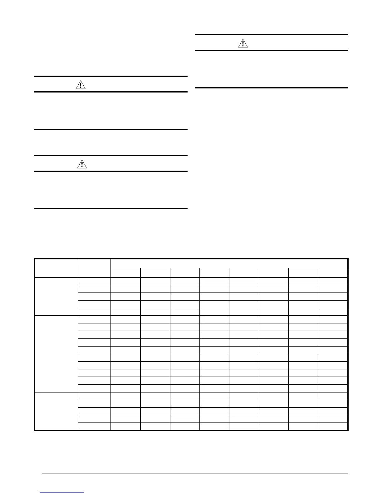
For optimum system performance and comfort, it may be
necessary to change the factory speed setting. See Table
1 below for factory settings. NOTE: This model has a High
Efficiency ECM Motor with 5 speed taps.
WARNING:
To avoid electric shock, personal injury, or death,
turn off the electric power at the disconnect or the
main service panel before making any electrical
connections.
1. Disconnect all electrical power to the unit and remove
the service panel.
CAUTION:
Label all wires prior to disconnection when
servicing controls. Wiring errors can cause
improperanddangerousoperation.Verifyproper
operation after servicing.
2. Locate the orange, black and blue wires terminated to
the blower motor. The black wire controls the low speed
cooling and heating operations, the blue wire controls
high speed cooling and heating operations and the
orange wire controls the electric heating operation.
CAUTION:
To avoid personal injury or property damage,
make certain that the motor leads cannot come
into contact with any metal components of the
unit.
3. Verify the required speed from the airflow data found
in Table 1. Place appropriate wire on the appropriate
motor speed tap for the required airflow.
4. Check all factory wiring per the unit wiring diagram and
inspect the factory wiring connections to be sure none
loosened during shipping or installation.
2-Speed Outdoor Fan Motor
(Select Models)
If the unit utilizes a 2-speed condenser fan motor, this
motor will operate on low speed when in low cooling/
heating, and on high speed when in high cooling/heating.
Ambient Sensor Mounting
For optimum performance of the heat pump system, the
ambient sensor (Figure 6 (page 9)) must be mounted
on the outside of the unit.
1. Remove the mounting bracket and all hardware included
in the packet.
2. Remove star bushing from 7/8” hole in corner panel of
the unit.
MODEL
NUMBER
MOTOR
TAP
EXTERNAL STATIC PRESSURE DROP (IN WC)
0.1 0.2 0.3 0.4 0.5 0.6 0.7 0.8
Q5RF-X24KA
Tap T1* 570 555 498 442 382 — — —
Tap T2** 810 765 721 675 625 555 495 —
Tap T3*** 1180 1140 1100 1050 1000 650 900 840
Tap T4 1302 1260 1220 1172 1127 1090 1035 985
Tap T5 1450 1410 1377 1335 1293 1245 1205 1160
Q5RF-X36KA
Tap T1* 875 832 775 715 659 599 555 —
Tap T2** 1267 1229 1181 1135 1099 1045 994 790
Tap T3 1380 1340 1305 1260 1220 1180 1130 1075
Tap T4*** 1440 1400 1365 1320 1280 1235 1195 1145
Tap T5 1500 1460 1420 1380 1340 1290 1250 1210
Q5RF-X48KA
Tap T1* 1030 980 950 900 860 810 765 725
Tap T2 1275 1225 1195 1145 1105 1055 1015 975
Tap T3** 1525 1504 1460 1422 1380 1353 1305 1271
Tap T4*** 1710 1665 1638 1609 1575 1530 1493 1449
Tap T5 1790 1760 1727 1701 1665 1627 1587 1553
Q5RF-X60KA
Tap T1* 1140 1094 1051 1005 954 901 850 802
Tap T2 1375 1340 1310 1252 1235 1172 1160 1108
Tap T3** 1691 1659 1623 1586 1544 1504 1468 1424
Tap T4*** 1722 1692 1653 1615 1579 1539 1498 1454
Tap T5 1841 1804 1771 1731 1703 1659 1614 1578
* Denotes factory set low cooling & heating speed
** Denotes factory set high cooling & heating speed
*** Denotes factory set auxillary heating speed
Table 1. Airflow Data
 Loading...