Operator’s manual
Optima 51 / M51 / M56 / M57T / 60T
32
Dynapôle Ludres/Fléville, 166 rue Ampère/BP 60093 - 54714 LUDRES - FRANCE - Tél.+33 (0)3 83 25 69 60 - Fax. +33 (0)3 83 26 12 85
Operation and maintenance
4 2Attachmentofthemachinetothetractor/cv
Do not stand or work between the tractor/cv and machine
when hitching
Step 1 : Two methods of attachment:
-Method 1: with a Quick Mounting Frame or Automatic Mounting Frame
(see chapter 1, paragraph <types of chassis mounting>)
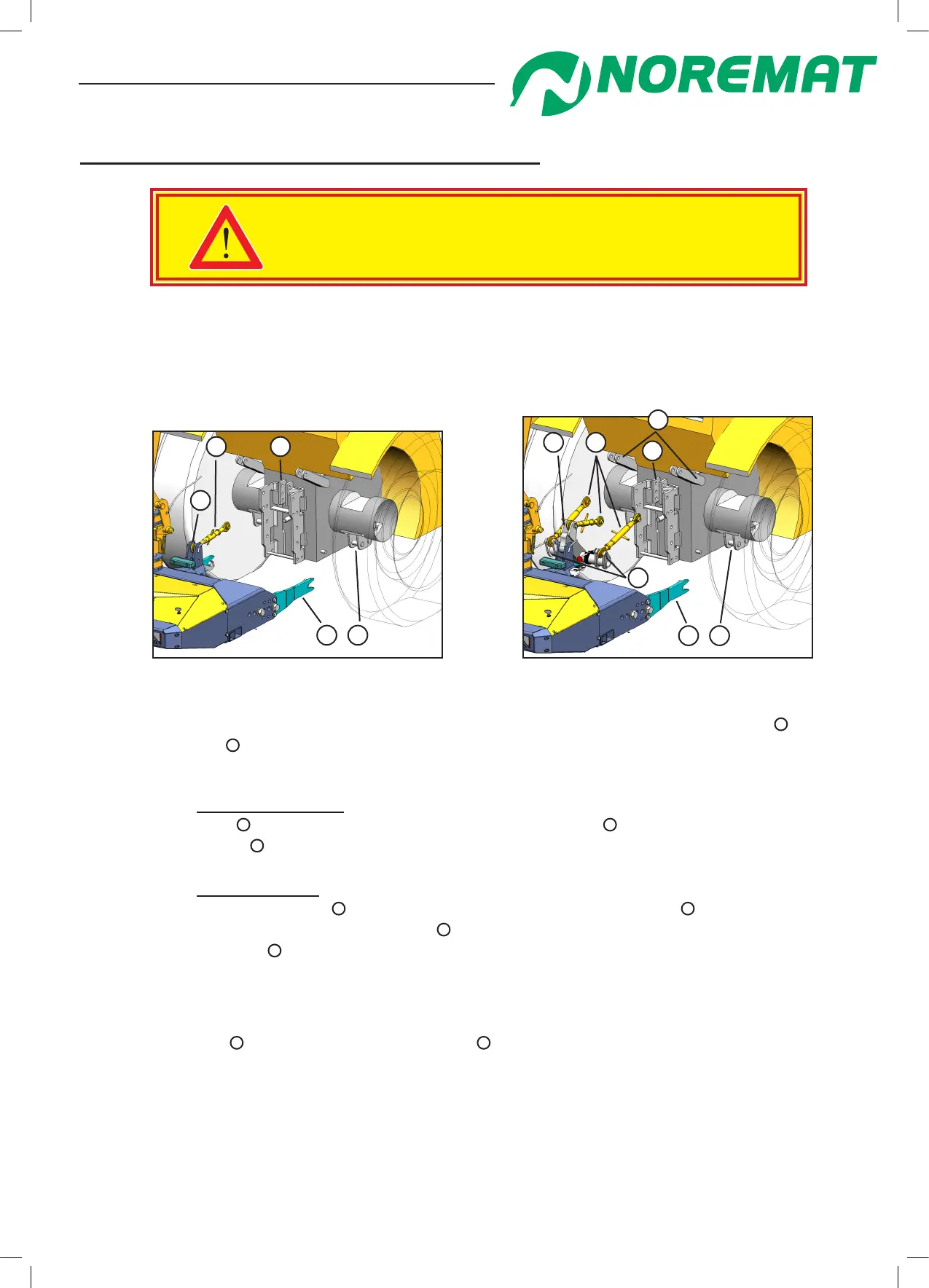
gure 2.14 : mounting without palonnier
4 5
1 2
3
gure 2.15 : mounting with palonnier
3 4
6
1 2
7
5
- on at ground, reverse the tractor/cv slowly to the machine and align the mounting arms
1
with the
receiving brackets
2
under the tractor axles.
- apply the parking brake.
for attachment without a palonnier (gure 2.14) :
- t a top link
4
between the top-link bracket on the machine
3
and the top-link bracket
on the tractor
5
- the top link should be inclined upwards towards the tractor/cv.
for attachment with a palonnier (gure 2.15) :
- t an adjustable top-link
4
between the central point on the palonnier
3
and the top-link bracket on the tractor
5
, in the same way t the outside adjustable links
to the palonnier
7
. Ensure that the tractor’s lift arms are fully raised.
- For the correct adjustment of the palonnier position refer to chapter 1,
paragraph <Adjustment of the 3-point linkage palonnier>
- Release the tractor/cv brakes and adjust the links so that the tractor is pulled rearwards to engage
the mounting arms
1
, with the under-axle brackets
2
.
-Secure or t and tighten the under-axle mounting points. (Depending on type)
-The position of the frame should be at 90degrees to the ground (gure 2.19) to ensure that the tool
guarding will work satisfactorily. If not, adjust the palonnier links.
- Go to Step 2