Operator’s manual
Optima 51 / M51 / M56 / M57T / 60T
33
Dynapôle Ludres/Fléville, 166 rue Ampère/BP 60093 - 54714 LUDRES - FRANCE - Tél.+33 (0)3 83 25 69 60 - Fax. +33 (0)3 83 26 12 85
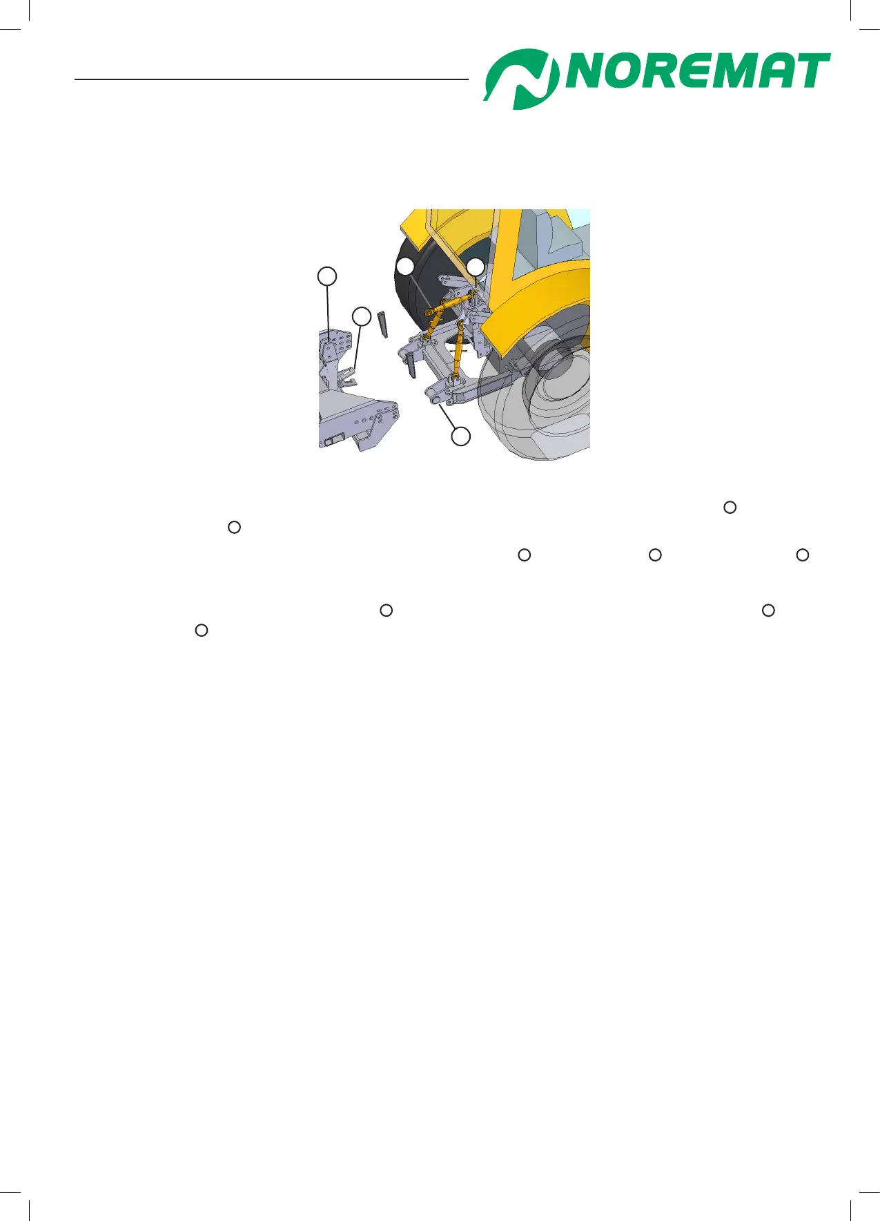
- Method 2 : ‘C’ mounting interface for multi-purpose frame already tted (gure 2.16)
(See chapter 1, paragraph <types of chassis mounting>)
gure 2.16
3
5
4
1
2
- On at ground, reverse the tractor slowly into the best position to engage the ‘C’ hooks
4
with the
multi-purpose frame
5
.
- Apply the tractor/cv brakes and connect the adjustable link
2
to the machine
1
and to the tractor
3
.
The central top link must slope upwards towards the tractor
- Release the brakes and adjust the links
2
to reverse the multi-purpose frame on the tractor
5
into
the ‘C’ interface
4
.
- Place the locking keys in the slots and then drive in with sensible use of a hammer.
(ATTENTION: risk of metal splinters; wear hand and eye protection.)
- The position of the frame should be at 90 degrees to the ground (gure 2.19) to ensure that tool
guarding will work satisfactorily.
- Go to phase 2
Step 2 :
Read the notice supplied with the driveshaft. This notice conforms to a decree No 81-293 dated March
31st 1981. Proof of conformity is found in this notice to ‘work code’ R233-62.
Install the driveshaft assembly.
If it is necessary to shorten the driveshaft, follow the enclosed instructions very carefully.
Step 3 :
Mount the hand control unit securely in the cab in a comfortable position for the operator and in a way
that it does not interfere with the operation of other controls.
Step 4 :
Make sure that all levers are in neutral and engage the PTO to run at low speed. Operate the
movement control levers in order to free the delivery locking bars and remove them.
Operation and maintenance