6-050700 X2 13
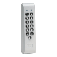
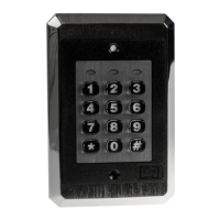
212iLW & 242iLW Standalone Keypad
Installation & Programming Manual
NOTE: You MUST wire a normally closed door switch, as shown in
Figure 8 on Page 11, for these functions to work properly.
1. (Wiring the alarm shunt) Using P1 (K2), connect the blue wire
(common) to common on the door switch. Connect the green
wire (normally open) to the normally closed contact on the door
switch.
2. (Wiring the propped door alarm) Using P2 (K3), connect the
green wire (normally open) to the positive on the alarm device.
Connect the blue wire (common) to the positive on the power
supply. Connect the negative on the alarm device to the negative
on the power supply.
3. (Wiring the forced door alarm) Using P3 (K4), connect the
green wire (normally open) to the positive on the alarm device.
Connect the blue wire (common) to the positive on the power
supply. Connect the negative on the alarm device to the negative
on the power supply.
Figure 10. Wiring and Integrated Accessory Relay Board
 Loading...