10
FURNACE
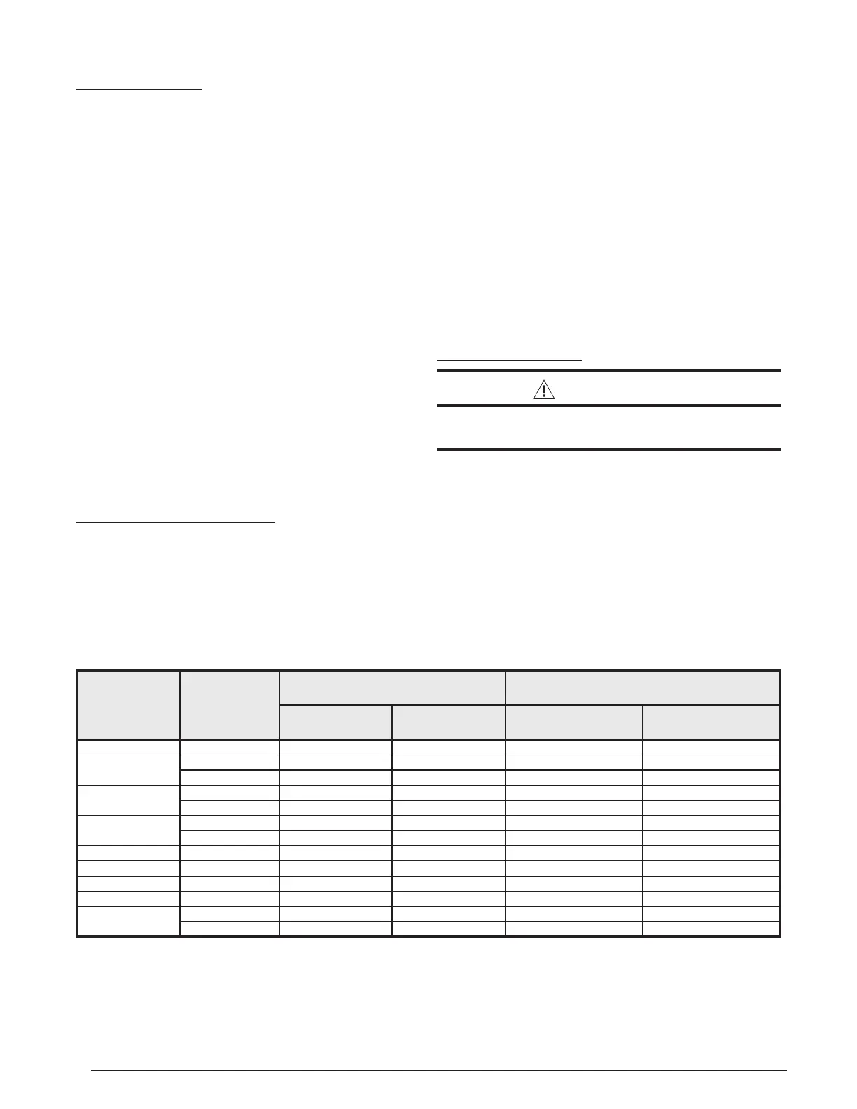
MODELS
(BTU)
FURNACE
INSTALLATION
SINGLE VENT PIPE LENGTH (FT.)
WITH 1 LONG RADIUS ELBOW†
DUAL VENT PIPE LENGTH (FT.)
WITH 1 LONG RADIUS ELBOW ON EACH PIPE†
OUTLET
2” DIAMETER
OUTLET
3” DIAMETER
INLET / OUTLET
2” DIAMETER
INLET / OUTLET
3” DIAMETER
38,000 Upflow 50 70 50 70
54,000
Upflow 70 90 70 90
Downflow 70 90 70 90
72,000
75,000
Upflow 50 90 50 90
Downflow 50 90 50 90
85,000
Upflow 60 90 60 90
Downflow 60 90 60 90
90,000 Upflow 60 90 60 90
108,000 Upflow N/A 90 N/A 90
115,000 Upflow N/A 90 N/A 90
118,000 Downflow N/A 90 N/A 90
120,000
Upflow N/A 90 N/A 90
Downflow N/A 90 N/A 90
†
NOTES:
1. Subtract 2.5 ft. for each additional 2 inch long radius elbow, 5 ft. for each additional 2 inch short radius elbow, 3.5 ft. for each additional 3 inch long radius elbow,
and 7 ft. for each additional 3 inch short radius elbow. Subtract 5 ft for each 2” tee and 8 ft for each 3” tee.
2. Two 45 degree elbows are equivalent to one 90 degree elbow.
3. This table applies for elevations from sea level to 2,000 ft. For higher elevations, decrease pipe lengths by 8% per 1,000 ft of altitude.
4. A long radius elbow’s centerline radius is equal to or greater than 1.5 times the vent diameter.
Table 1. Vent Pipe Lengths
Vent Pipe Material
Vent and combustion air pipe and fittings must be one of
the following materials in the list and must conform to the
indicated ANSI/ASTM standards.
MATERIALS STANDARDS
Schedule 40PVC ......................................................D1785
CPVC ........................................................................D1784
PVC-DWV .................................................................D2665
SDR-21 & SDR-26 ....................................................D2241
ABS-DWV .................................................................D2661
Schedule 40 ABS .....................................................F628
Foam / Cellular Core PVC ........................................ F891
*PolyPro
®
by DuraVent .............................................ULC-S636
*When using PolyPro
®
, all venting and fittings must be from the same
manufacturer with no interchanging of other materials. Refer to specific
instructions supplied with the PolyPro vent kits
When joining PVC to PVC, use cement that conforms to
ASTM standard D2564. PVC primer must meet standard
ASTM F656. When joining ABS to ABS, use cement that
conforms to ASTM standard D2235. When joining PVC
to ABS, use cement as specified in procedure from ASTM
standard D3138
In Canada, all plastic vent pipes and fittings including any
cement, cleaners, or primers must be certified as a system
to ULC S636. However this requirement does not apply to
the finish flanges or piping internal to the furnace.
Vent Pipe Length & Diameter
In order for the furnace to operate properly, the combustion
air and vent piping must not be excessively restrictive.
• The venting system should be designed to have the
minimum number of elbows or turns.
• Transition to the final vent diameter should be done as
close to the furnace outlet as practical.
• Always use the same size or a larger pipe for combustion
air that is used for the exhaust vent.
Table 1 (page 10) indicates the maximum allowable pipe
length for a furnace of known input rate, when installed with
piping of selected diameter and number of elbows. To use
the table, the furnace input rate, the centerline length and
the number of elbows on each pipe must be known.
When estimating the length of vent runs, consideration must
be made to the effect of elbows and other fittings. This is
conveniently handled using the idea of “equivalent length”.
This means the fittings are assigned a linear length that
accounts for the pressure drop they will cause. For example:
a 2” diameter, long radius elbow is worth the equivalent of
2.5 feet of linear run. A 90 degree tee is worth 7 ft.
The equivalent lenghts of tees and various elbows are listed
in Table 1. Measure the linear length of your vent run and
then add in the equivalent length of each fitting. The total
length, including the equivalent fitting lengths, must be less
than the maximum length specified in the table.
Vent Pipe Installation
CAUTION:
Combustion air must not be drawn from a
corrosive atmosphere.
This furnace has been certified for installation with zero
clearance between vent piping and combustible surfaces.
However, it is good practice to allow space for convenience
in installation and service.
• In the absence of local codes, the location of any
combustion air inlet relative to any vent terminal must
be at least 8 inches. This includes installations involving
more than one furnace.
• The quality of outdoor air must also be considered. Be
sure that the combustion air intake is not located near
a source of solvent fumes or other chemicals which can
cause corrosion of the furnace combustion system. (See
page 5 for a sample list of substances).
 Loading...