18
should be installed in the 1 5/8” hole prior to running the gas
pipe into the cabinet. No sealants are required.
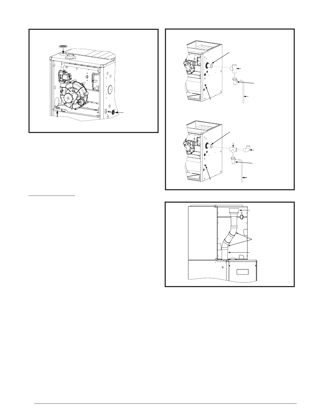
The 3/4” rubber grommet is used if venting out the left side of
the cabinet and the drain tube is routed through the blower
deck. Remove the plastic plug from the hole and install the
grommet before routing the drain tube.
PVC Components
IMPORTANT NOTES:
• Before permanently installing these components, it is
recommended you dry-fit them first to ensure proper
fit and alignment with other vent pipes.
• The 2” PVC components shown in Figure 20 are not
provided in the extra parts bag for *SC & *SL models.
However the PVC Trap (P/N 664659) can be purchased
thru your local distributor.
The 2” PVC tee, reducer, PVC Trap and 1/2” X 1/2” hose
barb are used when the inducer is rotated to vent out thru
the left or right side of the furnace cabinet. See Figure 20.
The 1/2” X 3/4” hose barb can be used to route the condensate
drain to the outside of the cabinet. It must be installed from
inside the cabinet with the threaded end inserted thru the 1
1/16” hole. The condensate drain should be connected to
the barbed end. Attach 1” PVC drain line to the threaded
end. See Figure 32 (page 30) or Figure 33 (page 31) for
hole location.
Typical Orientation
1. Install the PVC Tee vertically on the 2” vent pipe that is
extending out the side of the cabinet. Permanently bond
them together using appropriate primer and cement. Refer
to the typical orientation shown in Figure 20.
2. Install the reducer or PVC trap (if supplied) on the bottom
end of the PVC Tee. Permanently bond them together
using appropriate primer and cement.
3. Install the 1/2” x 1/2” hose barb on the 2” PVC reducer.
NOTE: Do not over tighten! Use an adequate amount of
Teflon tape on the threads. Do not use liquid sealants.
4. Verify all connections and joints for tight fit and proper
alignment with other vent pipes.
Figure 19. Rubber Grommets
Ø 3/4” Rubber
Grommet
ø 2 1/4” Rubber Grommet
(see note)
ø 7/8” Rubber
Grommet
1/2” x 3/4”
Hose Barb
2” PVC Elbow
(Field Supplied)
2” PVC Te e
1/2” x 3/4”
Hose Barb
2” PVC Pipe from Inline
Drain Assembly
(Not Included)
INSTALLATION OF PVC COMPONENTS
(TYPICAL ORIENTATION)
INSTALLATION OF PVC COMPONENTS
(ALTERNATE ORIENTATION)
2” PVC Te e
2” PVC Pipe from Inline
Drain Assembly
(Not Included)
1/2” T
Drain Line Attached
to PVC Trap
(Do Not Trap)
1/2” Tubing (Field Supplied)
Drain Line Attached
to PVC Trap
PVC TRAP
Not Included in
*SC & *SL Models
PVC TRAP
Not Included in
*SC & *SL Models
Figure 20. PVC Components
Figure 21. Optional PVC Pipe Installation
2” x 45
0
PVC
Elbow
2” PVC Pipe
2” x 3” PVC
Coupling
Coil Box
Alternate Orientation
1. Install the 2” PVC Tee horizontally on the 2” vent pipe that
is extending out the side of the cabinet. Permanently bond
them together using appropriate primer and cement. Refer
to the alternate orientation shown in Figure 20.
2. Install the 2” PVC Elbow on the end of the 2” PVC Tee.
Permanently bond them together using appropriate primer
and cement.
3. Install the reducer or PVC trap (if supplied) on the bottom
end of the PVC Tee. Permanenly bond them together using
appropriate primer and cement.
4. Install the 1/2” x 1/2” hose barb on the 2” PVC reducer.
NOTE: Do not over tighten! Use an adequate amount of
Teflon tape on the threads. Do not use liquid sealants.
5. Verify all connections and joints for tight fit and proper
alignment with other vent pipes.
 Loading...