11
• Route piping as direct as possible between the furnace
and the outdoors. Horizontal piping from inducer to
the flue pipe must be sloped 1/4” per foot to ensure
condensate flows towards the drain tee or PVC trap.
Longer vent runs require larger pipe diameters. Refer to
the Inducer & Venting Options section on page 15 for
additional information.
• If a Direct Vent (2-pipe) system is used, the combustion
air intake and the vent exhaust must be located in the
same atmospheric pressure zone. This means both pipes
must exit the building through the same portion of exterior
wall or roof as shown in Figure 38 (page 40) or Figure 43
(page 45).
• Piping must be mechanically supported so that its weight
does not bear on the furnace. Pipe supports must be
installed a minimum of every five feet along the vent run
to ensure no displacement after installation. Supports
may be at shorter intervals if necessary to ensure that
there are no sagging sections that can trap condensate. It
is recommended to install couplings along the vent pipe,
on either side of the exterior wall (Figure 38 or Figure 43).
These couplings may be required by local code.
• If breakable connections are required in the combustion
air inlet pipe (if present) and exhaust vent piping, then
straight neoprene couplings for 2” or 3” piping with hose
clamps can be used. These couplings can be ordered
through your local furnace distributor. To install a
coupling:
1. Slide the rubber coupling over the end of the pipe that is
attached to the furnace and secure it with one of the hose
clamps.
2. Slide the other end of the rubber coupling onto the other
pipe from the vent.
3. Secure the coupling with the second hose clamp, ensuring
that the connection is tight and leak free.
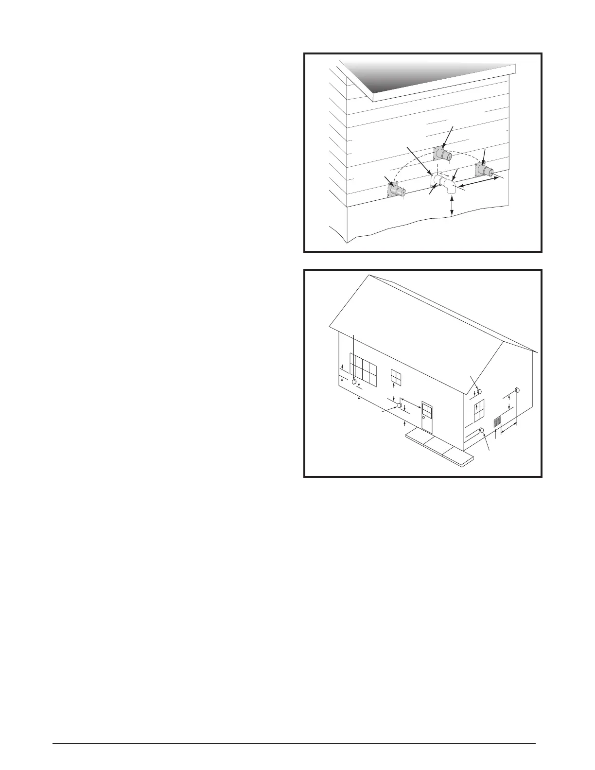
Outdoor Terminations - Horizontal Venting
• Vent and combustion air intake terminations shall be
installed as shown in Figure 7 & Figure 8 and in accordance
with these instructions:
• Vent termination clearances must be consistent with the
NFGC, ANSI 2223.1/NFPA 54 and/or the CSA B149.1,
Natural Gas and Propane Installation Code. Table 12
(page 39) lists the necessary distances from the vent
termination to windows and building air intakes.
• Vent and combustion air intake terminations must
be located to ensure proper furnace operation and
conformance to applicable codes. A vent terminal must
be located at least 3 feet above any forced air inlet located
within 10 feet. This does not apply to the combustion air
inlet of a direct vent (two pipe) appliance. In Canada,
CSA B149.1 takes precedence over these instructions.
See Table 12.
• All minimum clearances must be maintained to protect
building materials from degradation by flue gases. See
(Figure 8).
• For optimal performance, vent the furnace through a wall
that experiences the least exposure to winter winds.
• The vent termination shall be located at least 3 ft.
horizontally from any electric meter, gas meter, regulator
and any relief equipment. These distances apply ONLY
to U.S. installations. In Canada, CSA B149.1 takes
precedence over these instructions.
• Do not install the vent terminal such that exhaust is
directed into window wells, stairwells, under decks or into
Figure 7. Inlet & Exhaust Pipe Clearances
12” min. to maximum
expected snow level
(both pipes)
90° Elbow
Exhaust vent
option B
Exhaust vent
option A
Mounting kit faceplate
secured to wall with screws
(both pipes)
Combustion
air inlet
Exhaust vent
option C
18” Min.18” Min.
36” Max.36” Max.
8” Min.
36” Max.
(all positions)
Note 2
Mechanical draft
vent terminal
Direct vent
terminal
50,000 Btuh
or less
Forced air inlet
Direct vent
terminal - more
than 50,000 Btuh
Mechanical
draft vent
terminal
Mechanical
draft vent
terminal
Less
than
10 ft.
3 ft.
NOTES:
1. All dimensions shown are
minimum requirements.
2. Exterior vent terminations must
be located at least 12” above the
maximum expected snow level.
Note 2
4 ft
4 ft
12 in.
12 in.
9 in.
Note 2
Figure 8. Vent Locations
alcoves or similar recessed areas, and do not terminate
above any public walkways.
• If venting horizontally, a side wall vent kit is available
according to the pipe diameter size of the installation. 2
inch and 3 inch kits are available. Refer to the technical
sales literature for part numbers. Please follow the
instructions provided with the kit.
• Concentric vent termination kits are available for use with
these furnaces. Refer to the technical sales literature for
kit numbers.
• When the vent pipe must exit an exterior wall close to
the grade or expected snow level where it is not possible
to obtain clearances shown in Figure 7, a riser may be
provided as shown in Figure 9 (page 12). Insulation is
required to prevent freezing of this section of pipe. See
Table 3 (page 15) for vent freezing protection.
 Loading...