27
START-UP & ADJUSTMENTS
Pre-Start Check List
√ Verify the polarity of the connections are correct, the line
voltage power leads are securely connected and the
furnace is properly grounded.
√ Verify the thermostat wires (R, W, Y, & G) are securely
connected to the correct leads on the terminal strip of the
circuit board.
√ Verify the jumper on the Nordyne/UTEC board or
dipswitch on the Emerson board (for fan speed) on the
control board. See Figure 27 (page 25) and Figure 28
(page 25).
√ Verify the gas line service pressure does not exceed 10.0
inches of W.C., and is not less than 4.5 inches W.C. for
natural gas. For LP gas the line service pressure must
not exceed 14 in. W.C., and must not be less than 11.0
in. W.C.
√ Verify the roll-out and manual reset switch is closed. If
necessary, press the red button to reset a switch. DO
NOT install a jumper wire across a switch to defeat its
function. If a switch reopens on startup, DO NOT reset
the switch without identifying and correcting the fault
condition.
√ Verify the blower door is in place, closing the door switch
in the line voltage circuit.
√ Verify the gas line has been purged and all connections
are leak free.
Start-up Procedures
Do not perform these steps until all of the checks in the
previous steps have been completed:
1. Set the thermostat to the lowest setting.
2. Turn off all electrical power to the furnace.
3. Follow the Operating Instructions on the label attached to
the furnace.
4. Set the thermostat above room temperature and verify the
Operating Sequence (page 28).
5. After 5 minutes of operation, set the thermostat below
room temperature and verify steps 9 - 10 of the Operating
Sequence.
Verifying & Adjusting Input Rate
The input rate must be verified for each installation to prevent
over-firing of the furnace. NOTE: The input rate must not
exceed the rate shown on the furnace rating plate. At altitudes
above 2,000 feet, it must not exceed that on the rating plate
less 4% for each 1,000 feet. To determine the exact input
rate, perform the following procedures:
1. Shut off all other gas fired appliances.
2. Start the furnace and run it for at least 3 minutes.
3. Measure the time (in seconds) required for the gas meter
to complete one revolution.
4. Convert the time per revolution to cubic feet of gas per
hour using Table 6 (page 36).
5. Multiply the gas flow rate in cubic ft per hr by the heating
value of the gas in Btu per cubic ft to obtain the input rate
in Btuh. See example.
EXAMPLE:
• Time for 1 revolution of a gas meter with a 1 cubic ft
dial = 40 seconds.
• From Table 6 read 90 cubic ft gas per hr.
• Local heating value of the gas (obtained from gas
supplier) = 1,040 Btu per cubic ft.
• Input rate = 1,040 x 90 = 93,600 Btuh.
6. The manifold pressure must be set to the appropriate
value for each installation by a qualified installer, service
agency or the gas supplier.
WARNING:
Do not attempt to drill the gas orifices. Use only
factory supplied orifices. Improperly drilled
orifices may cause fire, explosion, carbon
monoxide poisoning, personal injury or death.
a.) Obtain the manifold pressure setting required for
this installation by referring to Table 8 (page 37) for
Propane or Table 10 (page 38) or Table 11 (page
38) for Natural Gas.
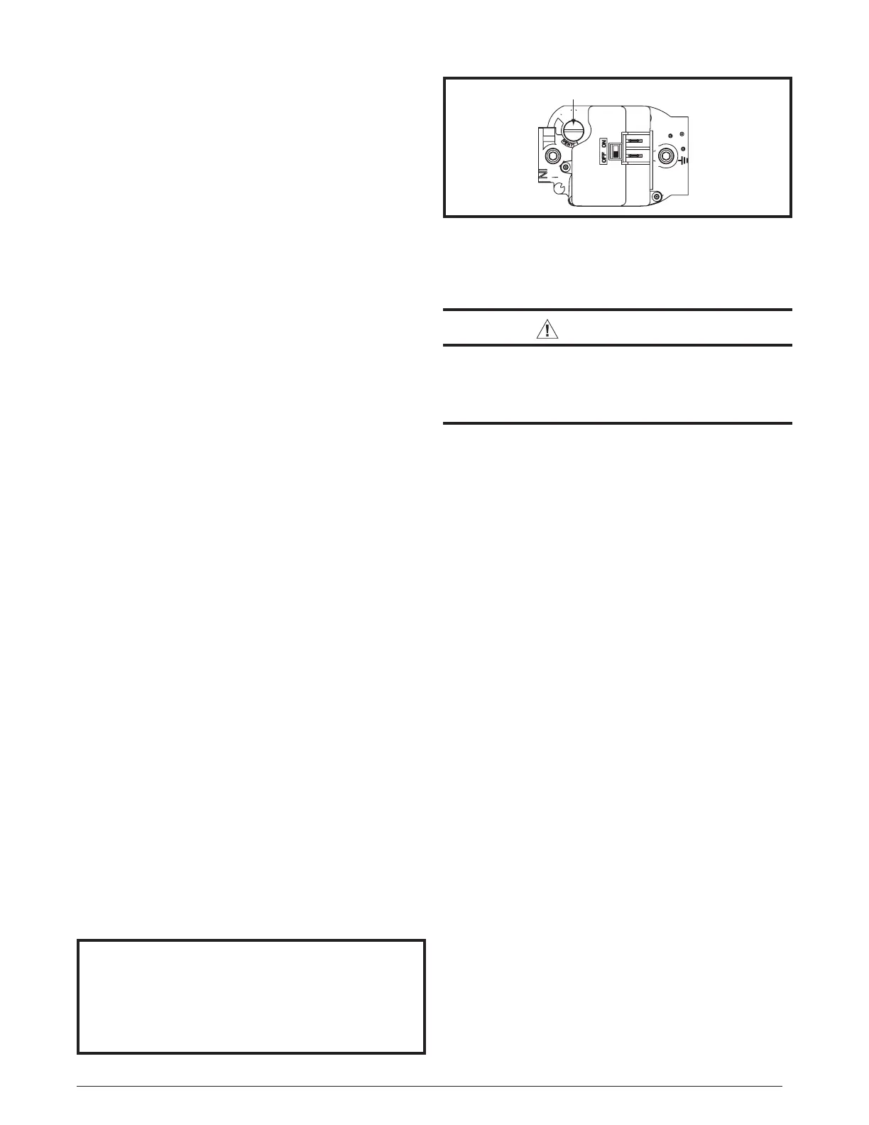
b.) Remove the regulator capscrew (Figure 31) from the
INLET side of the regulator.
c.) Slowly turn the adjustment screw inside the regulator
to obtain the appropriate manifold pressure.
NOTE: Turning the screw clockwise increases the
pressure and turning the screw counter-clockwise
decreases the pressure. To prevent backing the screw
all the way out from the valve, turn the screw slowly.
d.) Replace and tighten the regulator capscrew over the
adjustment screw.
Verifying & Adjusting Temperature Rise
After installation of the furnace, confirm the temperature rise
of the furnace is within the limits specified on the rating plate.
Any temperature rise outside the specified limits could result
in premature failure of the heat exchanger.
1. Place thermometers in the return and supply air stream
as close to the furnace as possible. The thermometer on
the supply air side must be shielded from direct radiation
from the heat exchanger to avoid false readings.
2. Adjust all registers and duct dampers to the desired position
and run the furnace for 10 to 15 minutes before taking
any temperature readings. The temperature rise is the
difference between the supply and return air temperatures.
For typical duct systems, the temperature rise will fall within the
limits specified on the rating plate with the blower speed at the
factory recommended setting. If the measured temperature
rise is outside the specified limits, it may be necessary to
change the speed of the blower.
NOTE: Lowering the blower speed will increase the
temperature rise and a higher blower speed will decrease
the temperature rise.
The furnace is equipped with a 5-speed ECM motor. Heating
and cooling speed selection is made by moving the switch on the
integrated control inside of the furnace. The furnace is shipped
Figure 31. Regulator Capscrew
 Loading...