25
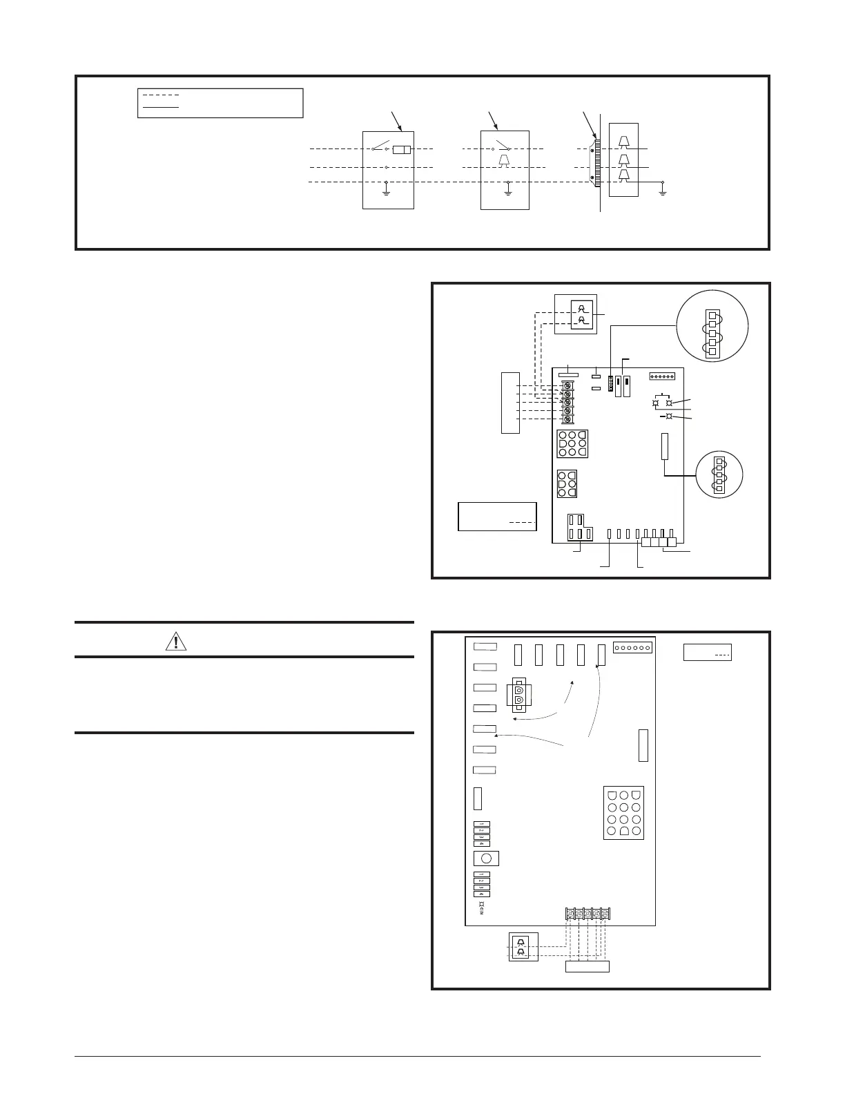
Figure 26. Line Voltage Field Wiring
Disconnect within
Sight of Furnace
Field Supplied
Panel Connector
Fused Service
Panel
Black (Hot)
White (Neutral)
Green or Bare (Ground)
Field Line Voltage Wiring
Factory Line Voltage Wiring
Ground
Ground
Junction Box (may be int. or ext. to the furnace). These connections can be made in the field supplied disconnect at the furnac
e.
NOTE: Connections made within the furnace burner compartment do not require a junction box.
Ground
Black
White
Black
White
Black
White
RCYGW
STATUS
FLAME
GREEN
RED
180
COOL
HEAT
120
90
60
YELLOW
BLOWER
OFF
DELAY
LOW
ML
MH
HIGH
EAC
L1
XFMR
HUM
COM
SPEED
SELECT
3 AMP
FUSE
24V
5
NEUTRALS
ROOM
THERMOSTAT
CONDENSING
UNIT
CONDENSING UNIT
CONTROL BOX
FIELD WIRING
LOW VOLTAGE
CONNECTION
R
C
Y
G
W
NOTE: The “Y” terminal
on the control board must
be connected to the
thermostat for proper
cooling mode operation.
Connect
R & W
Heating
Only
2
MOTOR
SPEED
TAPS
NEUTRAL LEADS
6 3
4
1
7
8
9
5
2
63
4
1
FAN
MH
L
H
ML
JUMPER PIN
SETUP
120
60
180
90
Figure 27. Nordyne/UTEC Low Voltage Field, Four-
wire Heating/Cooling Applications
Thermostat / Low Voltage Connections
• The furnace is designed to be controlled by a 24 VAC
thermostat. The thermostat’s wiring must comply with the
current provisions of the NEC (ANSI/NFPA 70) and with
applicable local codes having jurisdiction.
• The thermostat must be installed according to the
instructions supplied by the thermostat manufacturer.
Low voltage connections (24 VAC) from the thermostat
are wired to the terminal strip on the integrated control
in the furnace. Figure 27 contains the proper connections
for heating only (two-wire) and heating/cooling (four-wire)
applications. Recommended minimum wire gauge for
thermostat wiring is shown in Table 5 (page 24).
• The thermostat should be mounted about 5 feet above
the floor on an inside wall. DO NOT install the thermostat
on an outside wall or any other location where its
operation may be adversely affected by radiant heat from
fireplaces, sunlight, or lighting fixtures, and convective
heat from warm air registers or electrical appliances.
Refer to the thermostat manufacturer’s instruction sheet
for detailed mounting information.
Twinning
WARNING:
When servicing either twinned furnace, power
must be turned off on both furnaces. Failure to
comply may result in improper operation leading
to damage to the furnaces or personal injury!
Single stage furnaces are not supplied with a built-in twinning
capability. Other valuable features and enhancements were
made to the new control that made it necessary to remove
the twinning capability. For twinning of single stage furnaces
with 5-Speed ECM motors, a twinning kit is available for
purchase for use with the Nordyne/UTEC board. Refer to
the technical sales literature for part numbers. Please follow
the instructions provided with the kit.
Single stage furnaces are equipped with a fixed speed
blower; therefore, the twin terminal on the blower control
boards (Figure 29)(included in the Nordyne/UTEC board
twinning kit) may be used to twin the single stage furnaces.
The twinning system requires a relay (P/N 624843) in the
secondary furnace for proper twinning.
For proper twinning of fixed speed furnaces the following
criteria must be met:
• Both furnaces and motors must be the same size.
• Both motors must be on the same speed for cooling and
heating.
4
1
8
5
2
9
12 10
3
6
7
11
LINE-N
XFMR-N
CIRC-N
120V HUM-N
EAC-N
IND-N
IGN-N
EAC-H
120V HUM-H
CIRC-H
XFRM-H
LINE-H
T1
T2
T4
X
COM
T3
STATUS LIGHT
COOL FAN SPEED
FAULT RESET
HEAT FAN SPEED
CIRC FAN SPEED
OFF ON
TWIN TERMINAL
MOTOR
SPEED TAPS
3 AMP
FUSE
HUMIDIFIER
TA P
ELECTRONIC
AIR CLEANER
FIELD WIRING
LOW VOLTAGE
CONNECTION
NOTE: The “Y” terminal
on the control board must
be connected to the
thermostat for proper
cooling mode operation.
CONDENSING
UNIT CONTROL
BOX
A/C
CONDENSING
UNIT
Y W R G C
Y/
Y2 W R G C
ROOM THERMOSTAT
Connect R & W for heating only
Figure 28. Emerson Low Voltage Field, Four-
wire Heating/Cooling Applications
 Loading...