Northstar Explorer 660 Installation and Operation Manual 65
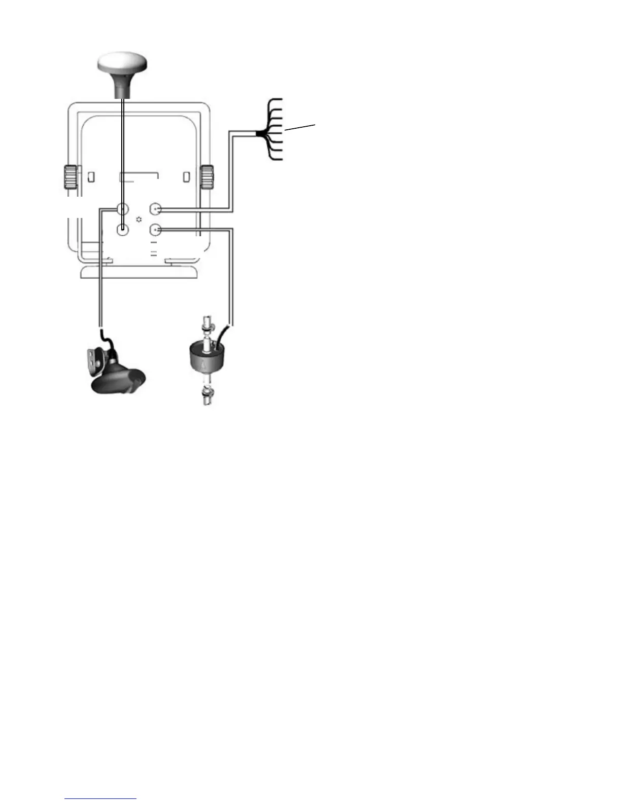
Optional fuel
sensor
Transom mount dual
frequency sonar
transducer
GPS antenna
White
connector
Black
connector
Blue
connector
Yellow con-
nector
Connections
Power/data cable
Pin Wire Function
1 Black Ground: power negative,
NMEA ground
Note: The cable has two wires with black
coverings, the black wire (pin 1) and the shield
(covered with heatshrink). These wires are con-
nected within the cable and
therefore it does not matter which black wire
you use.
2 Brown Power out, 9 V DC (NOT USED)
3 White NMEA out
4 Blue NavBus-
5 Red Positive power in, 10 to 35 V DC
6 Orange NavBus+
7 Yellow Auto power in (connect to red
wire [positive power in] to
enable Auto power).
8 Green External beeper or light out,
switched to ground, 30 V DC 200
mA maximum.
Power/data
cable