Installing the Charger
10
CHG-120 Instruction Manual 11/06/2002 PN 50641:B1
Installation Standards An installer should be familiar with the following standards:
• NEC Article 300 Wiring Methods.
• NEC Article 760 Fire Protective Signaling Systems.
• Applicable Local and State Building Codes.
• Requirements of the Authority Having Jurisdiction.
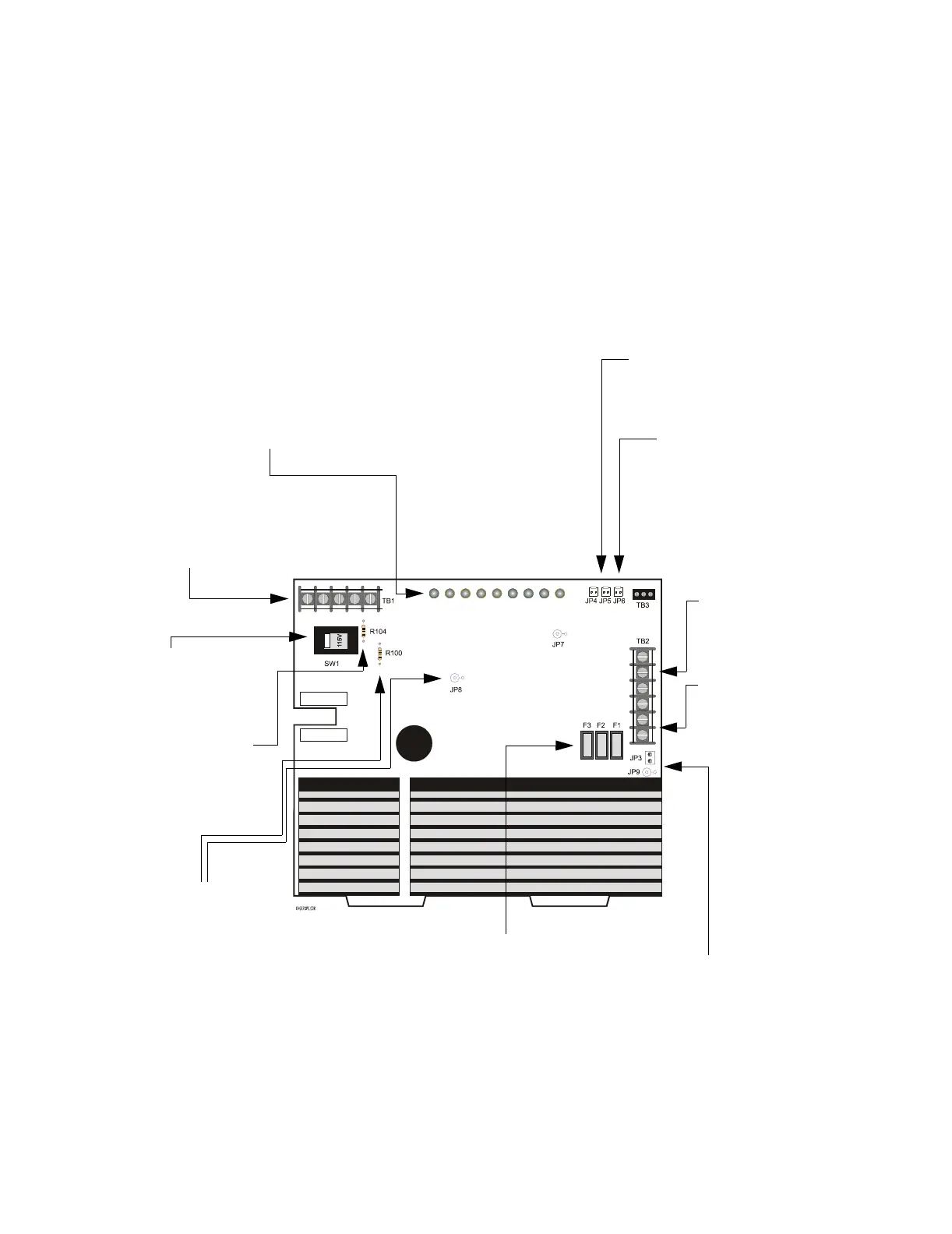
Charger Connections, Jumpers, and Switches
Figure 2 show all connections, jumpers, and switches needed to maintain, configure, and
operate the charger:
Figure 2 Charger Connections, Switches, and Jumpers
TB1 – AC Power (120 VAC
or 240 VAC (see
“Connecting AC Power to
the Charger” on page 11)
SW1 – Voltage Selection
Switch for selecting 120
VAC or 240 VAC operation
(See Figure 3 on page 11)
Resistor R104 – Cut to
disable ground fault
detection (refer to “Disable
Ground Fault Detection” on
page 19)
LED Status Indicators – Nine LEDs to
indicate status of the charger (see
“Understanding the LED Status
Indicators” on page 23)
Resistor R100 – Used
with JP8 to delay loss of
AC reporting (refer to
“Delay loss of AC
Reporting” on page 19)
JP4 – Open Collector Trouble Out
and JP5 – Open Collector Trouble In
(see “Trouble and Form-C Relay
Connections (Optional)” on page 20)
JP6 – Master Trouble In
(see “Trouble and Form-C
Relay Connections
(Optional)” on page 20)
TB3 – Form-C Trouble Relay
(see “Trouble and Form-C
Relay Connections (Optional)”
on page 20)
JP3 (AM-1 connector) and JP9 for
enabling an optional AM-1
ammeter. (see “Installing an AM-1”
on page 21)
Fuses F1, F2, and F3 – Replaceable
plugged fuses (see “Charger
Maintenance” on page 8)
TB2 – Output Circuits
1 and 2 (see
“Connecting the
Charger to a Load” on
page 16)
TB2 – Battery
Connections (see
“Connecting Batteries
to the Charger” on page
12)
AC Primary On
Charger Trouble
Earth Ground Fault
Hi Charge
Lo Charge
27V (battery voltage >27 VDC)
25V (battery voltage between 25-27 VDC)
23V (battery voltage between 23-25 VDC)
Low Battery (battery less than 23 VDC)