Installing the Charger
16
CHG-120 Instruction Manual 11/06/2002 PN 50641:B1
Connecting the Charger to a Load
This section provides two applications for connecting a charger to a load. While connecting
a charger to a load, observe the following precautions:
• Make sure all power sources are off to the charger and the load.
• Follow polarity when making connections.
Connecting the Charger to a Multiple Load You can connect a charger to multiple
loads, such as a main power supply, auxiliary power supply, amplifiers, and so forth, as
shown in Figure 9.
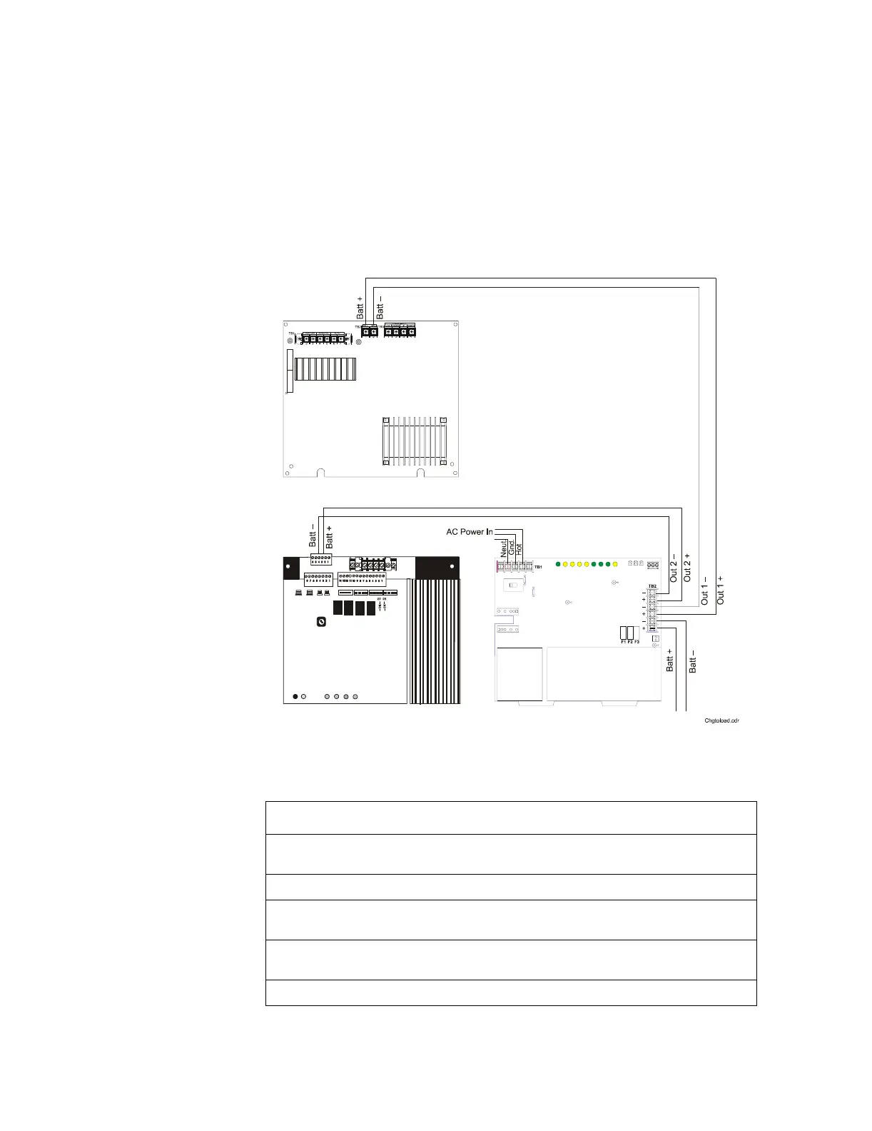
Figure 9 Typical Wiring for a Charger to a Multiple Load
To connect a charger as shown in Figure 9, follow these steps:
Step Action
1 Cut and remove resistor R104 to disable CHG-120 ground fault protection. Refer to Figure
12 for R104 location.
2 Cut jumper JP1 on the MPS-24A Circuit Board to disable the remote battery charger.
3 Connect the battery+ and battery– terminals of the power supply to the charger output
circuit (TB2: Out 1+ and Out 1–) as shown in Figure 9.
4 Connect the battery+ and battery– terminals of the amplifier to the charger output circuit
(TB2: Out 2+ and Out 2–) as shown in Figure 9.
5 Connect the batteries to the charger (for battery connections see Figure 5 or Figure 6).
CHG-120
AA-30
Amplifier
MPS-24A
Power Supply
Note: Figure 10 shows a
wiring diagram for tying the
load to battery terminals to
obtain additional current.
For example, the first
AA-120 draws 7 A, the
daisy-chained AA-30s draw
7 A, and the second
AA-120 draws 7 A of
additional current from the
batteries.