Installing the Charger
22
CHG-120 Instruction Manual 11/06/2002 PN 50641:B1
Installing a VM-1 You can connect a VM-1 across a charger output circuit. For example,
to install a VM-1 to measure voltage from charger output circuit 1, follow these steps:
1. Connect the positive lead to TB2 Out 2 (+). See Figure 14.
2. Connect the negative lead to TB2 Out 2 (–). SeeFigure 14.
3. Mount the VM-1 into a mounting slot on the front of the BB-55 battery box.
Installing an MPM-3 To install an MPM-3, follow these steps:
1. Connect the AM-1 (Figure 14).
2. Connect the VM-1 (Figure 14).
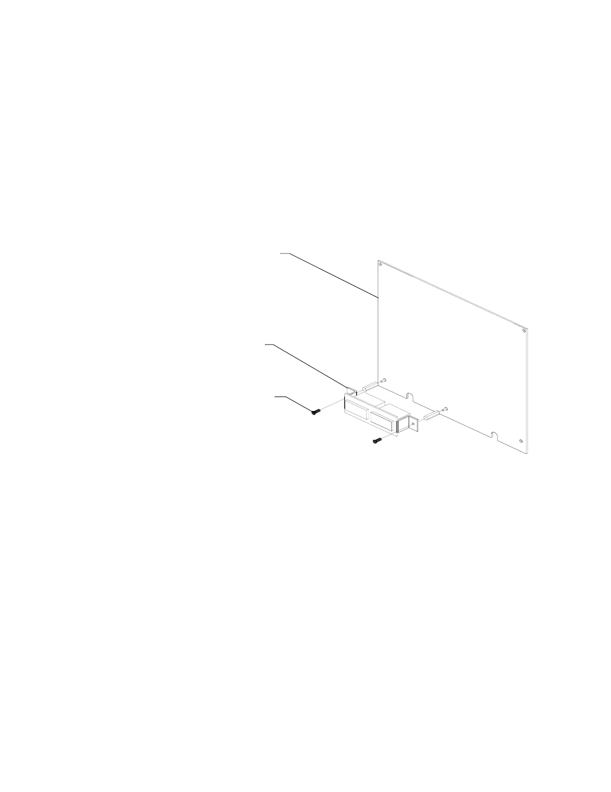
3. Mount the MPM-3 onto a power supply connected to your system, such as an
MPS-400 or MPS-24A (Figure 16).
Figure 16 Mounting an MPM-3
Power supply board
(MPS-400 or
MPS-24A)
MPM-3
MPM-3
Mounting screws
NOTE: The MPM-3 must be installed with supplied MPM-3 mounting hardware. Replace
the original mounting screws from the power supply with MPM-3 mounting screws prior
to installation.