Installing the Charger
CHG-120 Instruction Manual 11/06/2002 PN 50641:B1 17
Adding the Charger for Additional Current Each output on the charger is capable of
drawing 10 Amp maximum. 45 Amps is the maximum alarm current that can be drawn
from the batteries. To draw additional current from the charger, you can connect a load
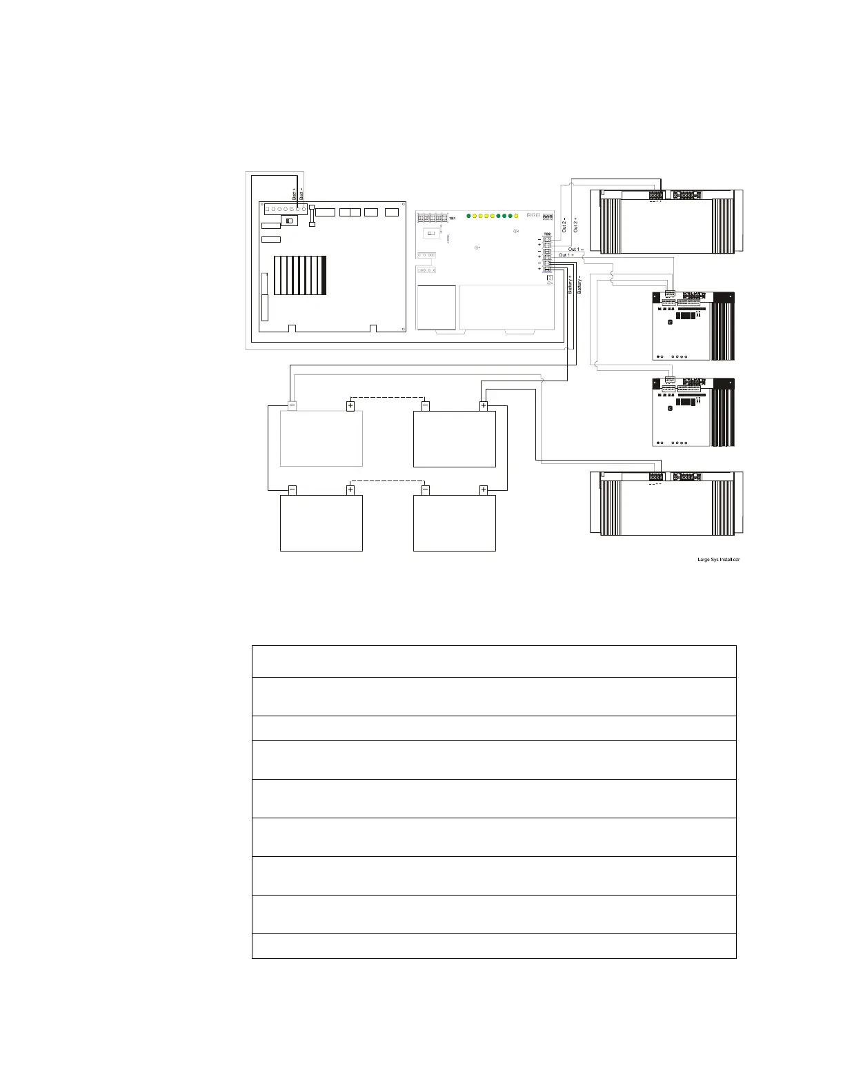
directly to the batteries as shown in Figure 10:
Figure 10 Typical Connections for Drawing Additional Current
To connect a charger as shown in Figure 10, follow these steps:
Step Action
1 Cut and remove resistor R104 to disable CHG-120 ground fault protection. Refer to Figure
12 for R104 location.
2 Cut jumper JP1 on the MPS-400 Circuit Board to disable the onboard battery charger.
3 Connect the Battery+ and Battery– terminals of the power supply to the charger Battery
output (TB2: Batt 1+ and Batt 1–) as shown in Figure 10.
4 Connect the Battery+ and Battery– terminals of the first AA-120 to the charger output circuit
(TB2: Out 2+ and Out 2–) as shown Figure 10.
5 Connect the Battery+ and Battery– terminals of the first AA-30 to the charger output circuit
(TB2: Out 1+ and Out 1–) as shown in Figure 10.
6 Connect the Battery+ and Battery– terminals of the second AA-30 to the Battery+ and
Battery– terminals of the first AA-30 as shown in Figure 10.
7 Connect the Battery+ and Battery– terminals of the second AA-120 to the batteries as shown
in Figure 10.
8 Connect the batteries to the charger.
55 AH/60 AH
12 VDC
55 AH/60 AH
12 VDC
55 AH/60 AH
12 VDC
55 AH/60 AH
12 VDC
MPS-400
Power Supply
Charger
First
AA-120
Second
AA-30
First
AA-30
Second
AA-120