Installing the Charger
18
CHG-120 Instruction Manual 11/06/2002 PN 50641:B1
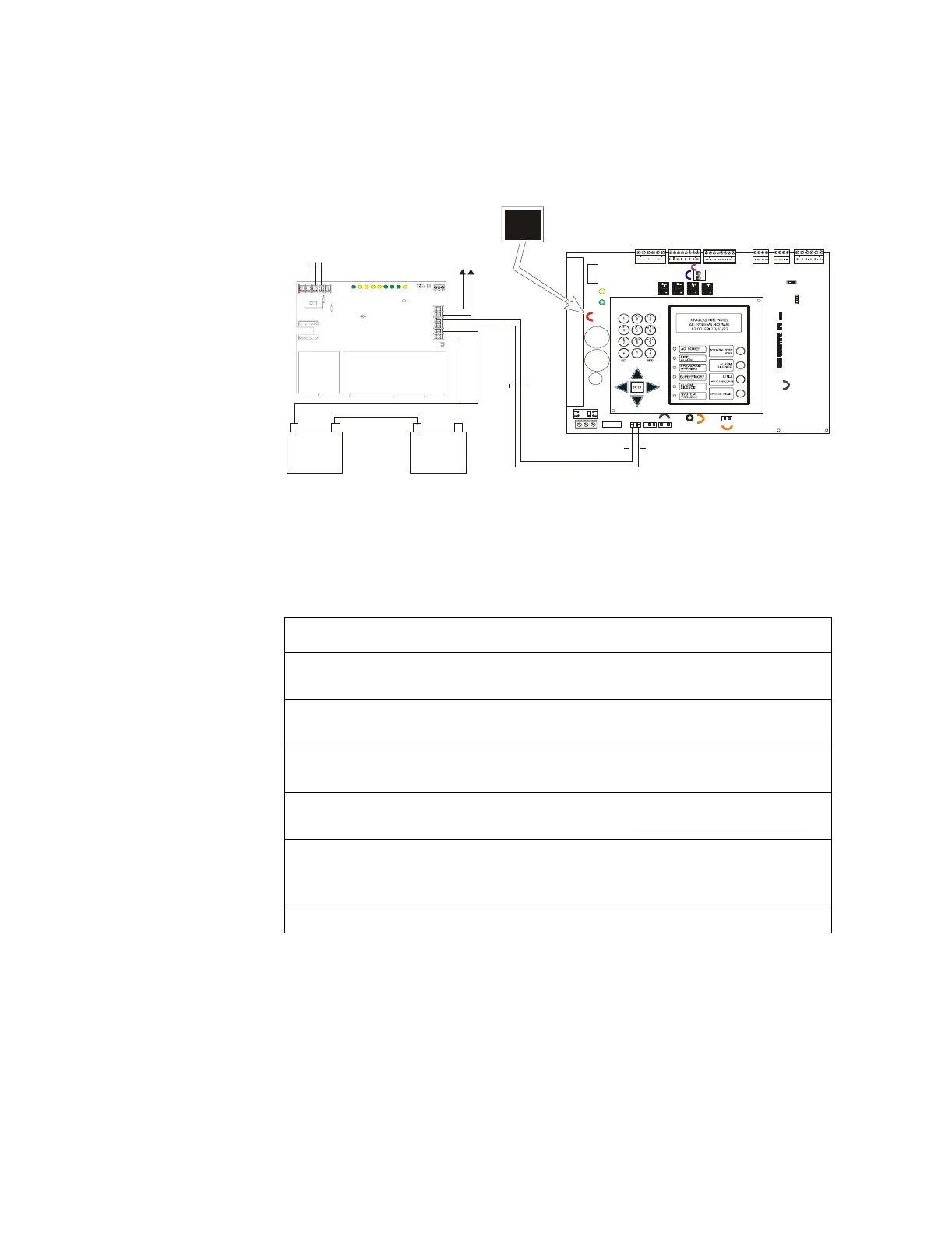
Connecting the Charger to an AFP-200: A charger can be connected to multiple loads,
such as the AFP-200 and auxilary equipment by disabling the local charger. Disable the
local charger by cutting jumper JP2.
Figure 11 Typical Wiring of a Charger to an AFP-200
To connect the charger to an AFP-200 unit follow these steps:
Step Action
1 Make certain that the AFP-200 Control Panel Main Circuit board is Revision G or
higher before proceeding with the charger connection.
2 Cut and remove resistor R104 to disable CHG-120 ground fault protection. Refer
to Figure 12 for R104 location.
3 Cut jumper JP2 on the AFP-200 Main Circuit Board to disable the FACP battery
charger. Refer to Figure 11 for JP2 location.
4 Connect battery cable from J3 on AFP-200 to the Charger Output Circuit [TB2:
(Out 1+ and Out 1 -)]. Refer to Figure 11 above. Be certain to observe polarity.
5 If required, connect the Battery + and Battery - terminals of any optional external
devices to the Charger Output Circuit (TB2: Out 2 + and Out 2 -). Refer to prior
Figure 10.
6 Connect the batteries to the charger. Refer to prior Figure’s 5 or 6.
JP2
JP7
JP5
SW3
SW2
JP3
JP9
JP1
J1
J2
J3 J4
JP6
JP2
Bat ter y –
25 AH
(12 V)
25 AH
(12 V)
–
+
–
+
TB2
TB1
–
+
–
+
–
+
Battery +
Battery Interconnect Cable
Charger
To Auxiliary
Equipment
AFP-200
AC Power In
Neut
Grd
Hot
Out 2 -
Out 1 +
Out 1 -
Out 2 +