DAA2 & DAX — P/N 53265:A1 8/24/2011 113
Installation DAA Digital Audio Amplifiers
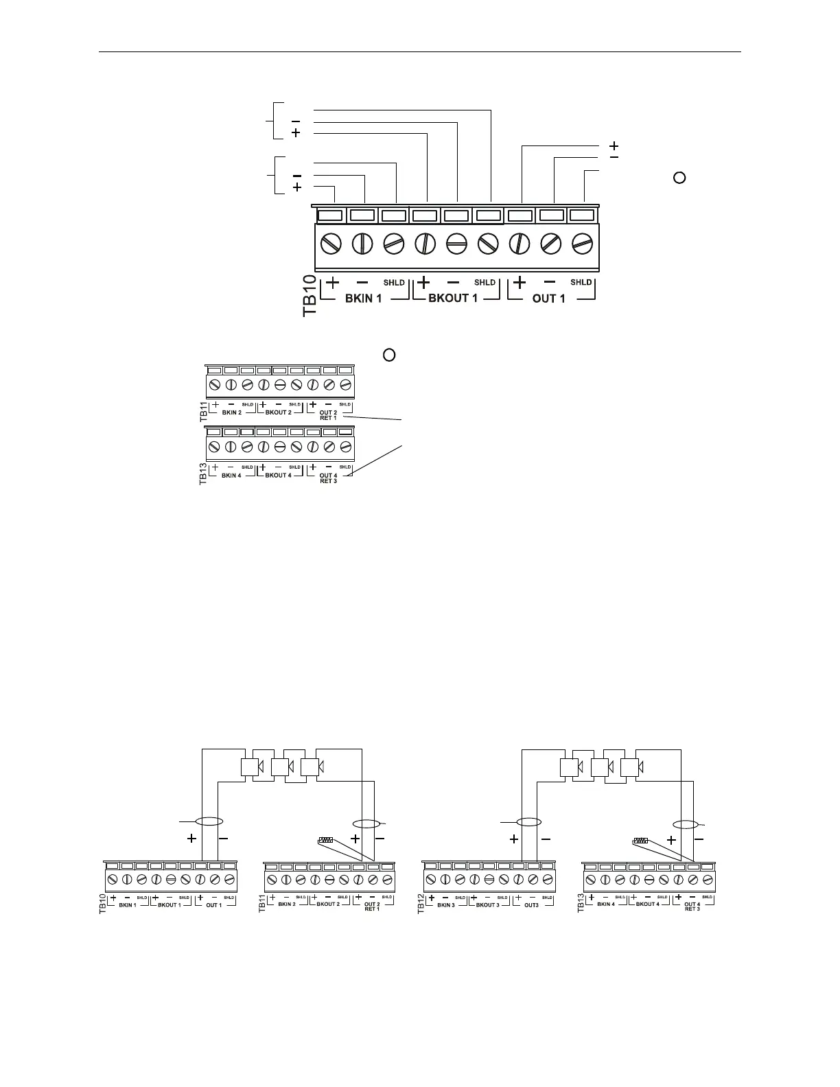
Speaker and backup connections are illustrated in Figure C.23.
In Normal (NAC) Mode
When a DAA’s Riser Mode is programmed N
ORMAL (NAC) (refer to VeriFireTools help file or the
DVC Digital Voice Command manual for programming description), the amplified signal from the
DAA may be connected directly to speakers. Following are illustrations of Class A and Class B
configurations (Figures C.24 and C.25).
Figure C.24 Two DAA Class A (Style Z) Circuits
TB10 (Ckt 1), TB11 (Ckt 2), TB12
(Ckt 3) and TB13 (Ckt 4) have the
same layout for circuit connections
with the following exceptions:
TB11: OUT 2
and
TB13 :OUT 4
DAABRDtb10.wmf
Backup In
Ckt 1,2,3,4
SHLD
Backup Out
Ckt 1,2,3,4
SHLD
High-level
audio Out,
Ckt 1, 2,
3, 4.
SHLD
may act as 4-wire returns for TB10 (OUT 1)
and TB12 (OUT 3) respectively. The board
has the additional silkscreen labels RET 1
and RET 3 at these terminals.
DAABRDtb11.wmf
DAABRDtb13.wmf
*
*
12-18 AWG twisted-pair
recommended
Figure C.23 Speaker Circuit and Backup Connections
Circuit 1
Circuit 2
Circuit 3
Circuit 4
High-
level
Return
High-
level
Out
R-10K
High-
level
Return
High-
level
Out
R-10K
DAABRDtb10.wmf
DAABRDtb11.wmf
DAABRDtb13.wmf
DAABRDtb12.wmf