DAA2 & DAX — P/N 53265:A1 8/24/2011 77
Installation Fiber Option Modules
5.3 Installation
5.3.1 DAA2 Installation
The DAA2’s power supply must be removed to install these option modules.
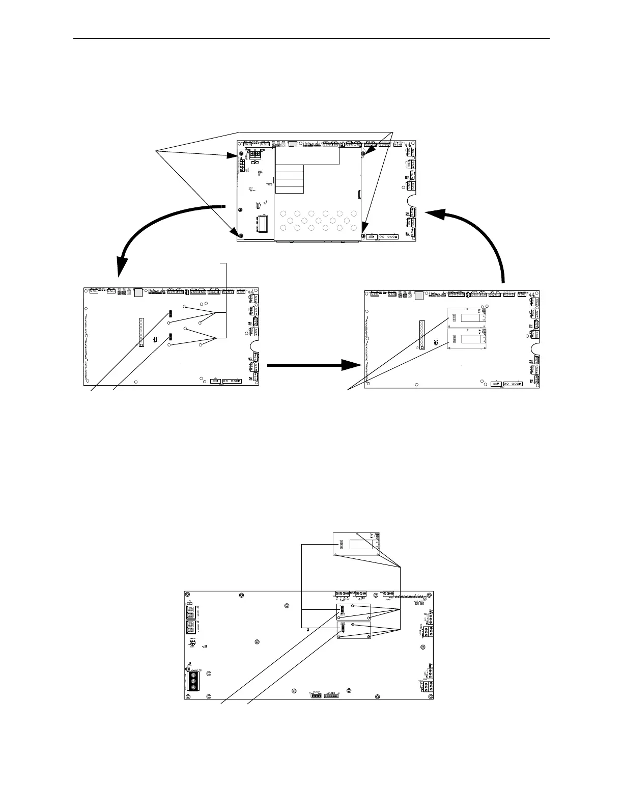
Figure 5.2 DAA2 Fiber Option Module Installation
5.3.2 DAX Installation
Install the fiber option modules as indicated.
Figure 5.3 DAX Fiber Option Module Installation
1. Remove power
supply. Remove
screws at points
indicated, and put
power supply aside.
2. Screw in option
module standoffs at
holes indicated. Each
module requires three
standoffs.
3. Align fiber option
module(s) over
standoffs and plug
into DAA2 at pin
connector(s). Screw
modules to
standoffs.
Pin connectors
4. Reposition power supply
and screw to standoffs.
Fiber option modules
J10
J9
Plugging a fiber option module into J9 disables TB2 (wire DAP A).
Plugging a fiber option module into J10 disables TB3 (wire DAP B).
Pin Connectors
Fiber
option
module
1. Attach standoffs (p/n 42206) for each
card (included with option module) at
the three points indicated.
2. Align option module over the
standoffs and plug into DAX at pin
connectors.
3. Screw module to standoffs with three
screws (p/n 38134) included with
option module.
Pin connectors
J3
J2
Plugging a fiber option module into J2 disables TB1 (wire DAP A).
Plugging a fiber option module into J3 disables TB2 (wire DAP B).