76 DAA2 & DAX — P/N 53265:A1 8/24/2011
Fiber Option Modules Layout
2. Establish the dB loss for each connector and splice. Sum all the losses.
3. Total the attenuation factors obtained in steps 1 and 2. This will provide an approximate
attenuation total. The actual attenuation should be measured end-to-end with fiber-optic
industry standard equipment.
DS-FM and DS-SFM
The maximum attenuation:
6.5dB for multi-mode with 50/125 micrometer cable @ 1310 nm.
10dB for multi-mode with 62.5/125 micrometer cable @ 1310 nm.
30dB for single-mode with 9/125 micrometer cable @ 1310 nm.
DS-SFM/Single-mode fiber DVC/DAA Connection
The maximum attenuation:
17dB for single-mode with 9/125 micrometer cable at 1310 nm going from the
DS-SFM to the fiber DVC or fiber DAA.
4dB for single-mode with 9/125 micrometer cable going from the fiber DVC or
fiber DAA to the DS-SFM
The minimum attenuation:
12dB going from the DS-SFM to the fiber DVC or fiber DAA.
DS-RFM/Multi-mode fiber DVC/DAA Connection
Attenuation going from the fiber DVC or fiber DAA to the DS-RFM:
2dB maximum for multi-mode with 50/125 micrometer cable @ 850 nm for the
DS-RFM.
4dB maximum for multi-mode with 62.5/125 micrometer cable @ 850 nm for
the DS-RFM.
Attenuation going from the DS-RFM to the fiber DVC or fiber DAA:
12dB minimum*, 16dB maximum for both cable types.
*If the length of the fiber run results in an attenuation of less than 12dB, a suitable
attenuator must be used.
5.2 Layout
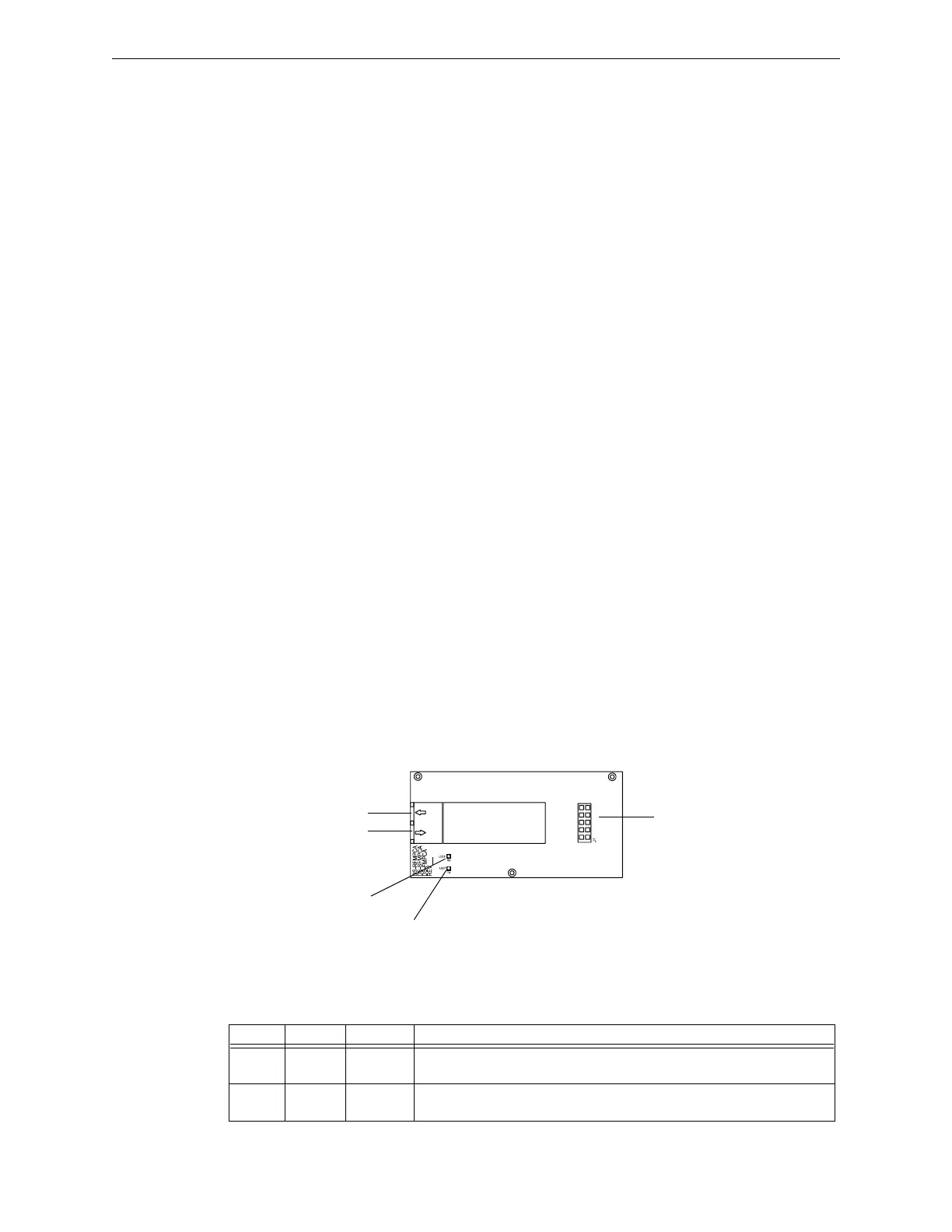
The DS-FM, DS-SFM and DS-RFM look the same. The silkscreened board names that do not
apply will be crossed off.
Figure 5.1 Fiber Conversion Module
.
LED # NAME COLOR DESCRIPTION
1 TX Green Illuminates while data is transmitted on the digital audio port. Light will
flicker, turning on when activity is detected and off when it is not.
2 RX Green Illuminates while data is received on the digital audio port. Light will
flicker, turning on when activity is detected and off when it is not.
Table 5.2 DS-FM LED Indicators
Fiber out
Fiber in
LED2 RX
LED1 TX
J1 Pin Connector