DAA2 & DAX — P/N 53265:A1 8/24/2011 97
Overview DAA Digital Audio Amplifiers
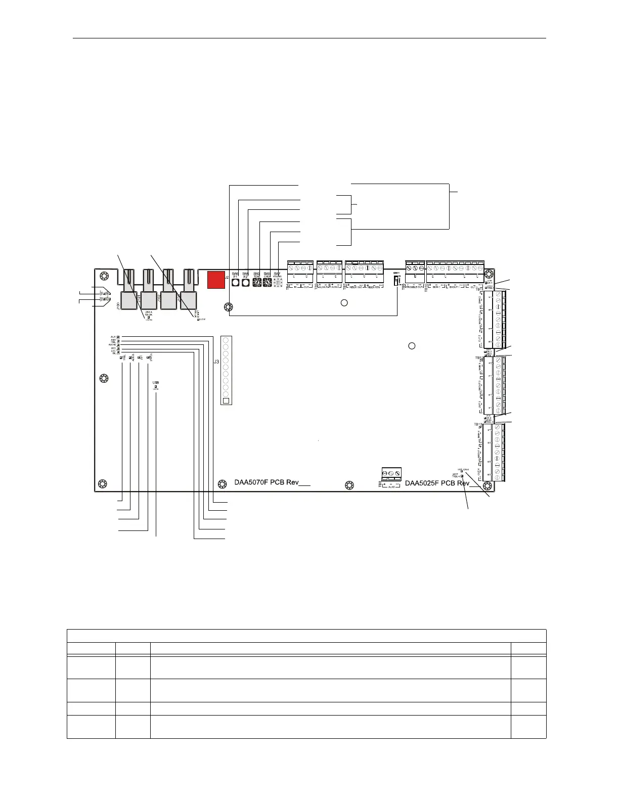
Indicator and Switch Locations
Switches and LED indicator locations are illustrated in Figure C.5. The connections for the smaller
front board, the DAA-PS, are the same for all DAAs, and are illustrated in Figure C.3, “LED
Indicator, Jumper and Switch Locations”.
Figure C.5 LED Indicator and Switch Locations, Fiber Boards
Indicators
Diagnostic colored LEDs indicate various conditions and troubles. Table C.3 lists and describes
each.
DAA Board
LED Indicators.
Refer to Table C.3
on page 98
Switches. Refer to
Table C.4 on
page 99
ONES
TENS
F2
F1
VOLUME
TRBL 1
ON 1
TRBL 2
ON 2
TRBL 3
ON 3
TRBL 4
ON 4
LED
Indicators.
Refer to
Table C.3 on
page 98
DAA_f_brd1.wmf
See also “Pushbutton
Controls” on page 121
See also
“Configuration” on
page 120
4WIRE
RXA
TXA
RXB
TXB
LINK B
RX OK
LINK A
RX OK
AUX
AL BUS
FFT
TRBL
AMP FAIL
STATUS
LOCSIL
RST
AUDIO
USB
DAA Board
LED Name Color Description LED #
EFB Yellow Illuminates steadily when an earth fault has been detected at digital audio port DAP B. LED is on
wire versions only.
1
EFA Yellow Illuminates steadily when an earth fault has been detected at digital audio port DAP A. LED is on
wire versions only.
2
AMP FAIL Yellow Illuminates steadily while audio amplifier failure detected. 4
ON 4 Green Illuminates steadily while analog signal is on speaker circuit 43, or while 200Hz tone is on speaker
circuit 4.
5