DAA2 & DAX — P/N 53265:A1 8/24/2011 107
Installation DAA Digital Audio Amplifiers
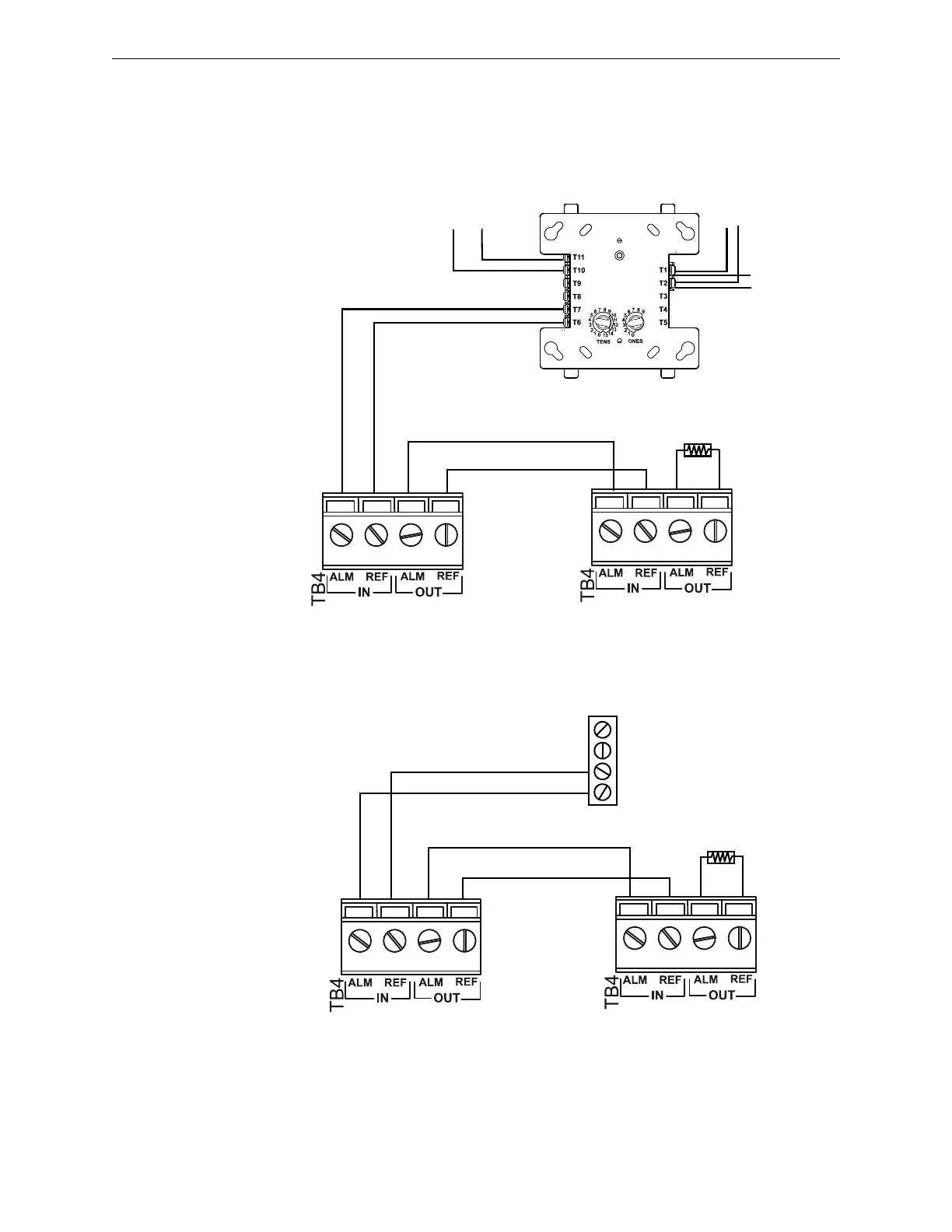
Connecting the Alarm and Trouble Buses
Alarm Bus
The DAA general alarm connections are used to receive general alarm messages from an FACP via
an SLC device, or via the Notification Appliance Circuit of an FACP or power supply.
Figure C.15 Alarm Bus Connections to FCM-1
Figure C.16 Alarm Bus Connections to NAC
Refer to the SLC manual and specific panel or power supply manual for more information.
FCM-1*
ALARM Bus to next DAA
ELR-47K,
1/2 watt
resistor
DAA
FZMFCMtpHa.wmf
DAABRDtb4.wmf
TB4
TB4
14-18 AWG twisted-pair
recommended
Program the control module at the
FACP with an appropriate alarm
Type ID per the FACP manual.
Alarm Bus requires 16VDC
at 20mA to activate.
To Power
Supply
+
-
SLC
from
FACP
SLC to
next device
+
-
+
-
+
-
*If the SLC device does
not match the one in this
figure, refer to the SLC
manual appendix, which
contains wiring conver-
sion charts for type V
and type H modules.
NAC Circuit
A -
A +
B +
B -
ALARM Bus to next DAA
DAABRDtb4.wmf
DAA
TB4
TB4
ELR per panel
or power
supply manual.
14-18 AWG twisted-pair
recommended
Listed compatible
panel or power
supply with onboard
NAC circuits.
Alarm Bus requires 16VDC
at 20mA to activate.