24 DAA2 & DAX — P/N 53265:A1 8/24/2011
DAA2 Digital Audio Amplifiers DAA2 Installation
CAB-4 Series
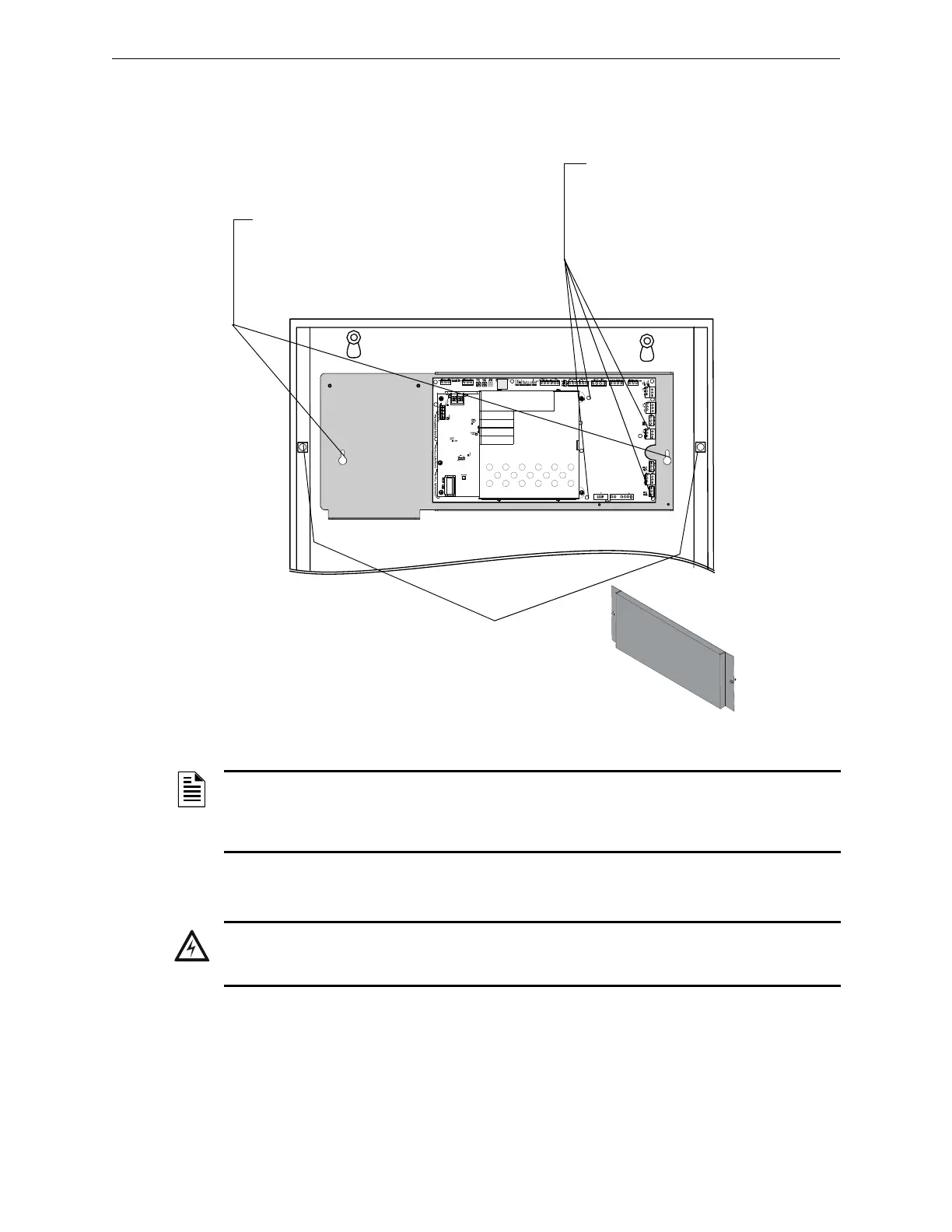
Figure 2.5 illustrates a typical DAA2 installation. A DP-1B dress panel, ordered separately, can be
used to cover the row.
Figure 2.5 DAA2 Cabinet Installation
2.2.2 Batteries
The DAA2 works with two 12 volt batteries. See Appendix B.1, “DAA2 Battery Calculations”, on
page 84 for current draw calculations to determine the battery size required for this installation.
Batteries for the DAA2 may be installed in any of the following configurations:
• In a CHS-BH1 battery chassis (12AH batteries only), designed for use with the DAA2
chassis.
• In the bottom of a CAB-4 series cabinet that holds the DAA2.
1. Place the DAA2 chassis over the chassis
standoffs at the locations indicated. Secure
with two 10/32 nuts.
DAA2mtgcab4.wmf
Using the hardware that
comes with the DP-1B
dress panel, attach it at the
points indicated.
DP-1B
DP-1B.wmf
Optional BDA-25/70V or Network Control
Module (wire or fiber NCM or HS-NCM)
Mounting:
1. Fasten four 2 3/8” steel 4-40 male/female
standoffs ( P/N 42227, included with the
DAA2) at the bottom of the chassis.
2. Position the card over the 4 fastening
points and secure with four 4-40 screws (P/N
2820-0039, included with the option card.)
Refer to page 38 for BDA harness
installation.
NOTE: Digital amplifiers can produce significant heat during their duty cycles. Different cabinets
can handle different amounts of heat. Refer to the Heat Dissipation Calculation document (53645)
to determine dissipation figures for the equipment you are installing, and match it with an
appropriate cabinet.
WARNING: Batteries contain sulfuric acid which can cause severe burns to the skin and eyes, and
can destroy fabrics. If contact is made with sulfuric acid, immediately flush skin or eyes with water for
15 minutes and seek immediate medical attention.