Mounting
Semi-flush Mount Backbox
21
Document 51264 Rev A2 6/14/00 P/N 51264:A2
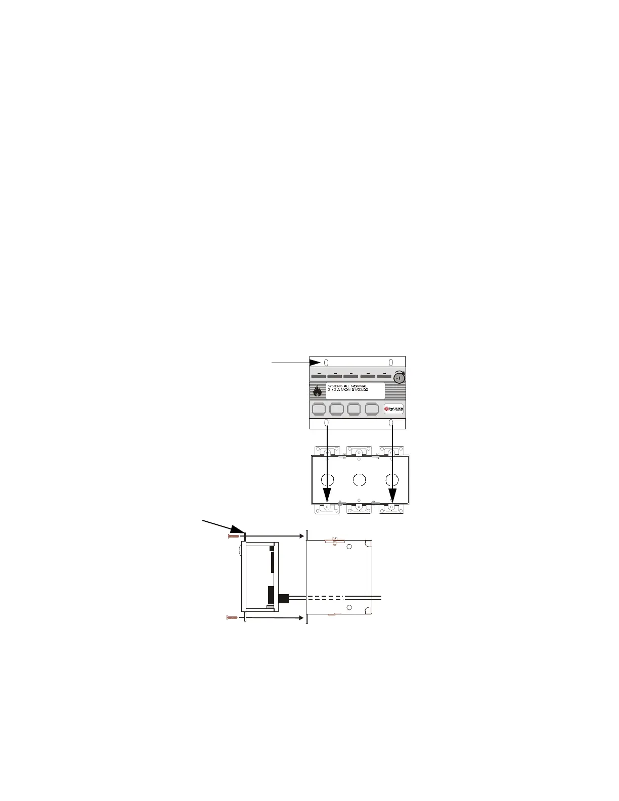
Mounting in Three Electrical Boxes Ganged Together
Remove the plug-in terminal blocks from the FDU-80 circuit board.
Connect the EIA-485 and power wiring into the terminal block positions
illustrated in Figure 1-2 on page 9, Figure 4-1 on page 23 and Figure 4-
2 on page 24. Plug the terminal blocks back into the P2 and P1 connec-
tors on the back of the annunciator. Set DIP switch SW1 for the desired
options. Refer to Figure 1-3 on page 12.
Carefully insert the FDU-80 into the three electrical boxes ganged
together and attach it using the four mounting holes on the FDU-80
flange and the four screws provided for this purpose. Replace the trim
ring and secure with the two screws which were previously loosened.
Adjust the plastic trim ring to the surface of the wall before tightening
the screws.
Do not overtighten.
Ack/Step
Silence Reset
Drill
Hold 2 sec.
FIRE ALARM ANNUNCIATOR
Alm . Silenc edSupe rvisor yTroubleAlarmAC Power
Figure 3-4: Mounting in 3 Ganged Electrical Boxes
FDU-80 flange
FDU-80 Three electrical boxes ganged together
flange
EIA-485 and
power wiring
FDU80flg.cdr
Lcd4xbox.cdr
Three ganged electrical boxes
3gngbox.cdr
mounting holes (4)
The FDU-80 can be surface mounted in
three gangable electrical switch boxes
connected together.
Important!
When installing conduit in
three ganged electrical boxes, use knock-
outs on the top or bottom. Installing conduit
on the sides or back of some boxes may
interfere with mounting of the FDU-80 in the
box.
www.PDF-Zoo.com