Electrical Connections
EIA-485 Connections
24
Document 51264 Rev A2 6/14/00 P/N 51264:A2
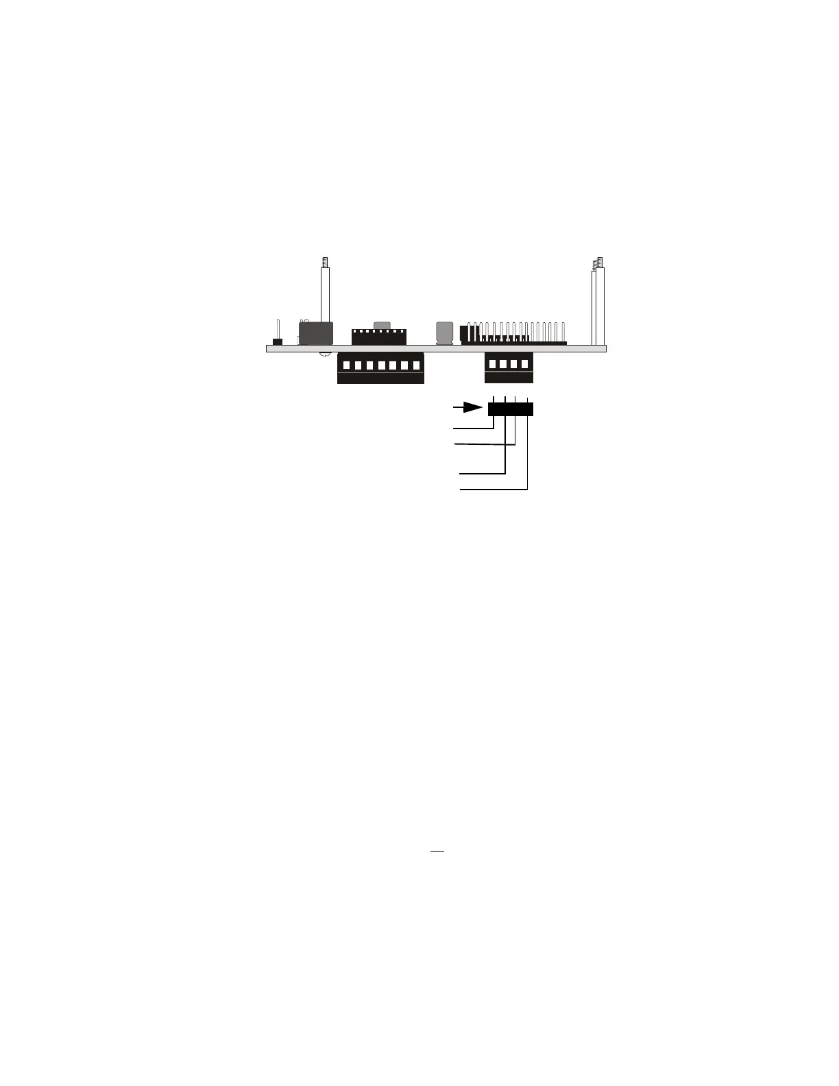
4.2 EIA-485 Connections
Notes:
1. All connections are power-limited and supervised
2. A maximum of 32 FDU-80 annunciators may be connected to
this circuit
3. 6,000 feet (1,800 m) maximum distance between the FACP and
first FDU-80, between each FDU-80 and return to the FACP
from last FDU-80
4. Use overall foil/braided-shielded twisted pair cable suitable for
EIA-485 applications (refer to “EIA-485 Shield Termination” on
page 25, for shield termination information). Six conductor
overall shielded wire may be used for the four EIA-485 wires
and the two power wires. It is, however, strongly recommended
that the power and communication wires be separate whenever
possible
5. Ferrite Core P/N FBD-1 is required to meet FCC Part 15 require-
ments if the EIA-485 wiring is not in conduit
6. The EIA-485 circuit is rated at 5.5 VDC maximum and 60 mA
maximum
7. The FDU-80 annunciator has resistors built into the circuit board
at the In (Terminals 2 & 4) and the Out (Terminals 1 & 3) for
impedance matching. There is no
need for the installer to add
impedance matching resistors
4 3 2 1
7 6 5 4 3 2 1
12345 6
78
Figure 4-2: EIA-485 Connection
P2
P1
+ EIA-485 OUT
+ EIA-485 IN
- EIA-485 OUT
- EIA-485 IN
FDU-80
in from FACP
Out to next FDU-80 or
return to host FACP if last or
only annunciator on the line
Ferrite Core P/N FBD-1 is required (see note 5)
FDU80Bdscdr
www.PDF-Zoo.com