Mounting
Surface Mount Backbox
22
Document 51264 Rev A2 6/14/00 P/N 51264:A2
3.3 Surface Mount Backbox
Remove the plug-in terminal blocks from the FDU-80 circuit board.
Connect the EIA-485 and power wiring into the terminal block positions
illustrated in Figure 1-2 on page 9, Figure 4-1 on page 23 and Figure 4-
2 on page 24. Plug the terminal blocks back into the P2 and P1 connec-
tors on the back of the annunciator circuit board. Set DIP switch SW1
for the desired options. Refer to Figure 1-3 on page 12.
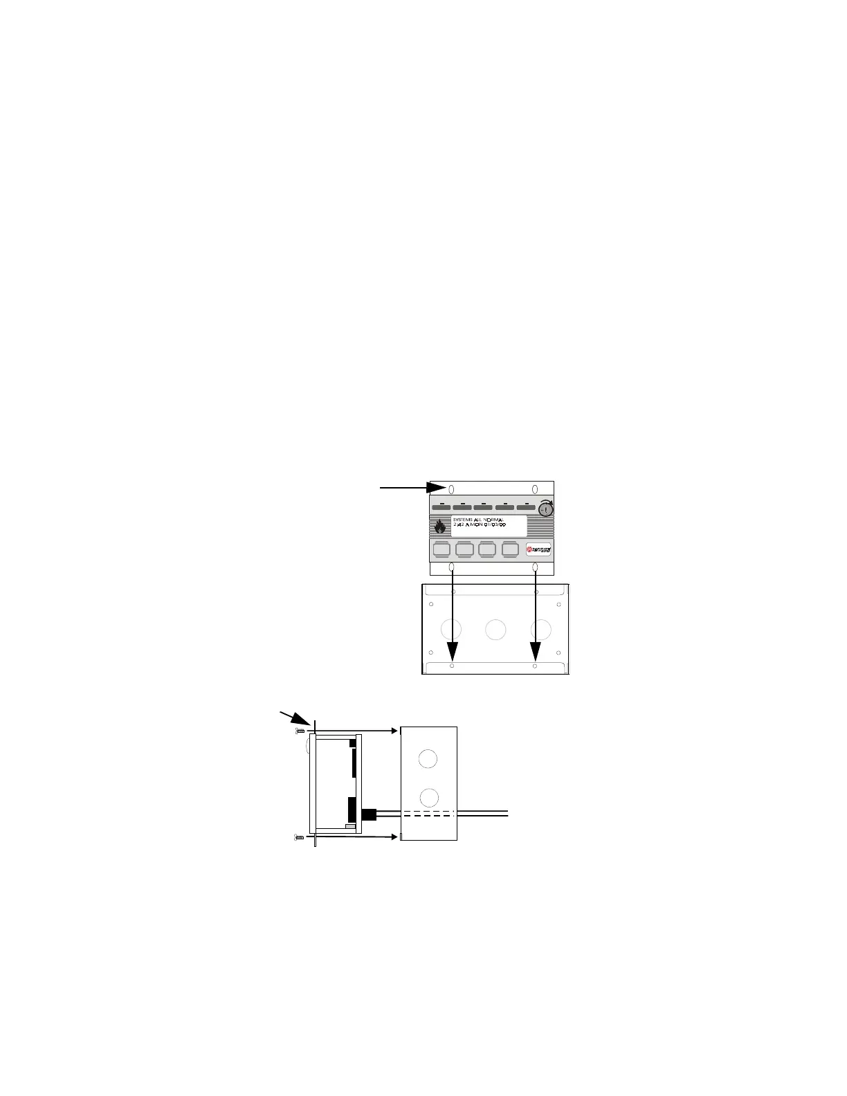
Carefully insert the FDU-80 into the three-gang electrical box and
attach it using the four mounting holes on the FDU-80 flange and the
four screws provided for this purpose. Replace the trim ring and secure
with the two screws which were previously loosened.
Do not
overtighten.
Ack/Step
Silence Reset
Drill
Hold 2 sec.
FIRE ALARM ANNUNCIATOR
Alm. Silenc edSupervisoryTroubleAlar mAC Power
Figure 3-5: Surface Mounting
FDU-80 flange
Mounting holes (4)
The FDU-80 can be surface mounted in
a three-gang electrical box, P/N SBB-3
or equivalent, with a minimum depth of
2.75".
FDU-80 Three-gang surface box P/N SBB-3
flange
EIA-485 and power wiring
FDU80flg.cdr
Sbb-3.cdr
Lcd40box.cdr
www.PDF-Zoo.com